
HALdrive X20
XY3-100 to Analogue Converter
HALdrive N20
NX-02 to Analogue Converter
Users Manual
© 2020-2026 by HALaser Systems
1
HALdrive X20
XY3-100 to Analogue Converter
HALdrive N20
NX-02 to Analogue Converter
Users Manual
© 2020-2026 by HALaser Systems
1

Table of Contents
1 Copyright.........................................................................................................................................................................................................3
2 History..............................................................................................................................................................................................................4
3 Safety................................................................................................................................................................................................................5
4 Overview.........................................................................................................................................................................................................6
5.1 Scanner Signals...................................................................................................................................................................................7
5.2 Galvo X and Y Signals.......................................................................................................................................................................8
5.3 Optional Power Supply Input.......................................................................................................................................................8
5.4 Initial Operation.................................................................................................................................................................................9
6.1 Scanner Signals................................................................................................................................................................................10
6.2 Power Supply....................................................................................................................................................................................11
6.3 Galvo X and Y Signals....................................................................................................................................................................11
6.4 Optional Power Supply Input....................................................................................................................................................11
6.5 Initial Operation..............................................................................................................................................................................13
7 E170Xbase...................................................................................................................................................................................................14
APPENDIX A – Wiring between HALdrive X20 and E1701D.....................................................................................................15
APPENDIX B – Wiring between HALdrive X20 and E1702S......................................................................................................16
APPENDIX C – Wiring between HALdrive X20 and E1803D.....................................................................................................17
APPENDIX D – IDC connector pin numbering..................................................................................................................................18
APPENDIX E – XY3-100 protocol description..................................................................................................................................19
APPENDIX F – Board dimensions...........................................................................................................................................................20
2

1 Copyright
This document is © by HALaser Systems.
E1701 boards, their hardware and design are copyright / trademark / legal trademark of HALaser Systems.
E1803D boards, their hardware and design are copyright / trademark / legal trademark of HALaser Systems.
HALdrive and HALscan, their hardware and design are copyright / trademark / legal trademark of HALaser
Systems.
XY3-100 is copyright/trademark by Laser Industry Association International.
All other names / trademarks are copyright / trademark / legal trademark of their respective owners.
3

2 History
Date
Changes in document
10/2023
IDC-connector pin counting clarified
10/2023
Type code description added
08/2023
Added description of NX-02 variant
05/2023
E170Xbase description added
04/2023
Connector description simplified
03/2023
Pin-names of XY3-100 interface clarified
01/2023
Added wiring for E1702S
01/2023
Extended power supply voltage range described
12/2022
Unused pinout removed
10/2022
Description of wiring with E1701D/E1803D extended/clarified
08/2022
Added diameter of holes in mechanical drawing section
04/2022
Maximum current for galvo outputs specified
12/2021
Pinout description extended, power supply wiring description added
06/2021
XY3-100 certified logo added
05/2021
Added pinout and description of HALdrive OEM
04/2021
Wiring schemes for E1701D and E1803D added
10/2020
Added description for 10V hardware variant
07/2020
Added section for initial operation
06/2020
Initial version
4

3 Safety
The hardware described within this document is designed to control a laser scanner system. Laser radiation
may effect a person's health or may otherwise cause damage. Prior to installation and operation compliance
with all relevant safety regulations including additional hardware-controlled safety measures has to be
secured. The client shall solely be responsible to strictly comply with all applicable and relevant safety
regulations regarding installation and operation of the system at any time.
Beside of that some laser equipment can be damaged in case it is controlled with wrong signals or signals
outside a given specification. Thus it is highly recommended to check the output generated by this hardware
using e.g. an oscilloscope to avoid problems caused by wrong configurations. This should be done prior to
putting a system into operation for the first time, whenever some parameters have been changed or whenever
any kind of software update was installed.
The hardware described here is shipped without any cover and without prefabricated equipment for electric
installation. It is intended to be integrated in machines or other equipment. It is not a device for use "as is", but a
component which is intended to be used as part of a larger device, e.g. for integration in a machine with own
housing or within an electrical cabinet. Prior to operation compliance with all relevant electric /
electromagnetic safety regulations including additional hardware-controlled safety measures has to be
secured. The client shall solely be responsible to strictly comply with all applicable and relevant regulations
regarding installation and operation of the system at any time.
The hardware described here is an electrostatic sensitive device. This means it can be damaged by common
static charges which build up on people, tools and other non-conductors or semiconductors. To avoid such a
damage, it has to be handled with care and including all relevant procedures (like proper grounding of people
handling the hardware, shielding/covering to not to let a person touch the hardware unwanted, proper
packaging in ESD-bags, ...). For more information please refer to related regulations and standards regarding
handling of ESD devices. The EMC Directive (2014/30/EU) does not apply to this hardware as it is not intended
for an end user (a person without knowledge of EMC) and as it is not otherwise made available on the market.
The Low Voltage Directive (2014/35/EU) does not apply to this hardware as the voltage supply is below the
50V AC / 75V DC limit.
This control board is considered partly completed machinery in accordance with the EU Machinery Directive
(2006/42/EC). It cannot operate independently and is intended to be integrated into a larger machine or
system. The final integrator is responsible for ensuring that the complete machine or system complies with all
applicable safety and regulatory requirements in the intended market (such as CE- certification).
This document describes the HALdrive digital XY3-100/NX-02 to analogue converter hardware but may
contain errors or may be changed without further notice.
5

4 Overview
This document describes the HALdrive X20 converter board, its electrical characteristics and usage.
This board is designed to receive digital XY3-100 scanner controller signals and to convert them to 2x
synchronous analogue output signals.
Furthermore it describes the HALdrive N20 converter board, its electrical characteristics and usage.
This board is designed to receive digital NX-02 scanner controller signals and to convert them to 2x
synchronous analogue output signals.
So both variants act as some kind of converter between two different signal types for controlling scanning
systems/scanheads.
This board is not a ready-to-use device but a component which is intended to be integrated in larger devices or
to be operated with an own housing. The board itself is customisable and can be adapted to work with other
transfer protocols too. In case of special requirements, contact us!
4.1 Features
The HALdrive converter boards provides the following features:
•
accepts 2D input signals in XY3-100 or NX-02 format (X and Y position data, Z is ignored if available)
•
synchronous output of analogue X and Y position data in +-5V.. +-10V range (values in between are
available on request)
•
20 bit output resolution
•
100 kHz sampling/output frequency
•
XY3-100 or NX-02 backchannel
•
instant-on, so there is no boot-up time until the device is available
•
input voltage range of +-15..+-24V, wider voltage range available on request
4.2 Type Code
Converter boards of type “HALdrive” make use of a defined name scheme which can be interpreted as follows:
HALdrive Irr
HALdrive
– the general name of the converter board
I
– interface to scanner controller card:
“
.
” or “
X
” – XY3-100 interface
“
N
” – NX-02 interface
rr
– digital resolution of the input
6
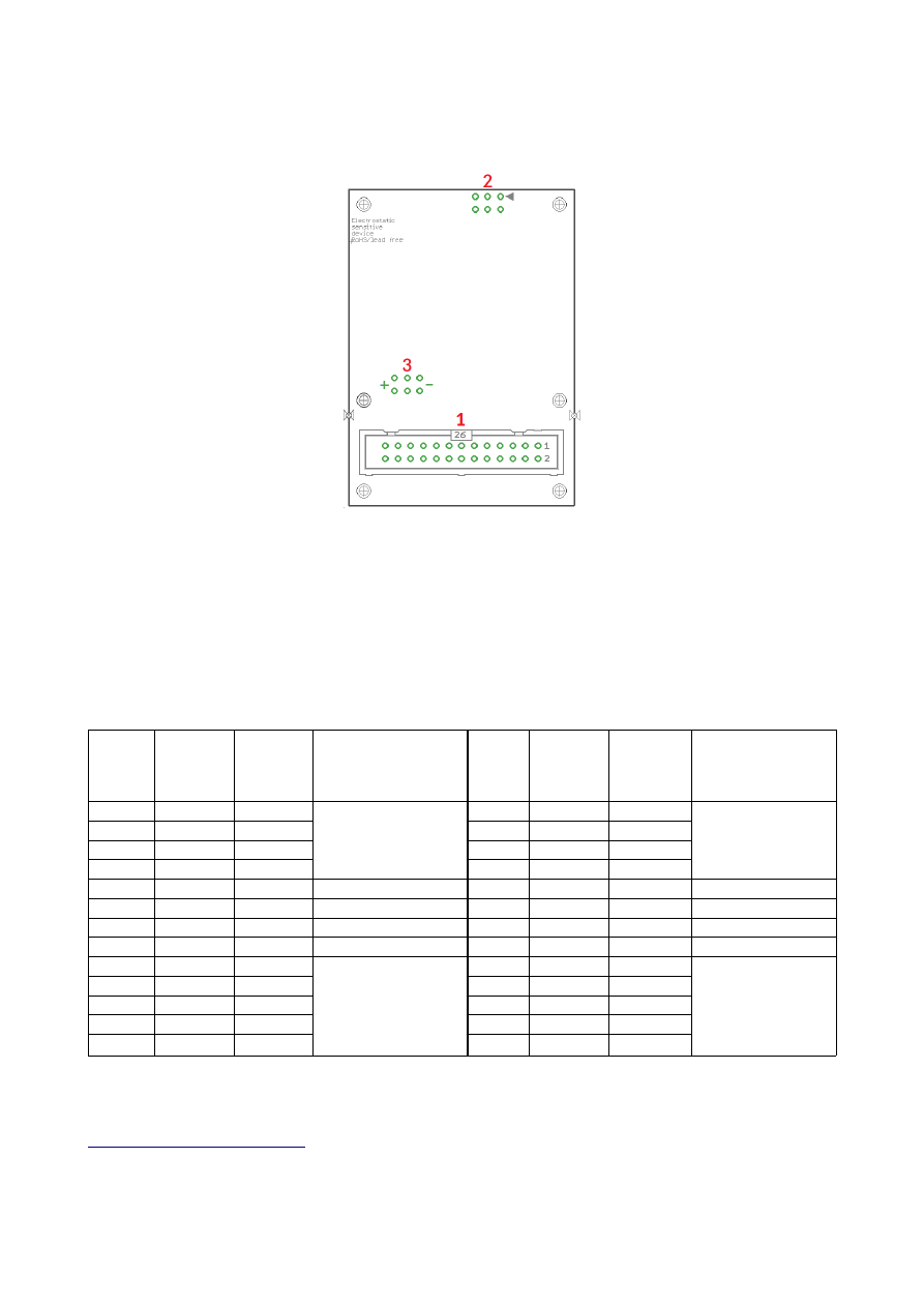
5 HALdrive X20 Board And Connectors
The XY3-100 board variant provides the following connectors:
1. XY3-100 interface for power supply and scanner input signals (as described below)
2. 2,54mm 6pin connector for Galvo-X and Galvo Y analogue output signals
3. Optional separate power supply input pin, when not already provided via connector (1)
5.1 Scanner Signals
The (optionally white) 26 pin connector expects the XY3-100 position signals and the power supply for the
HALdrive board:
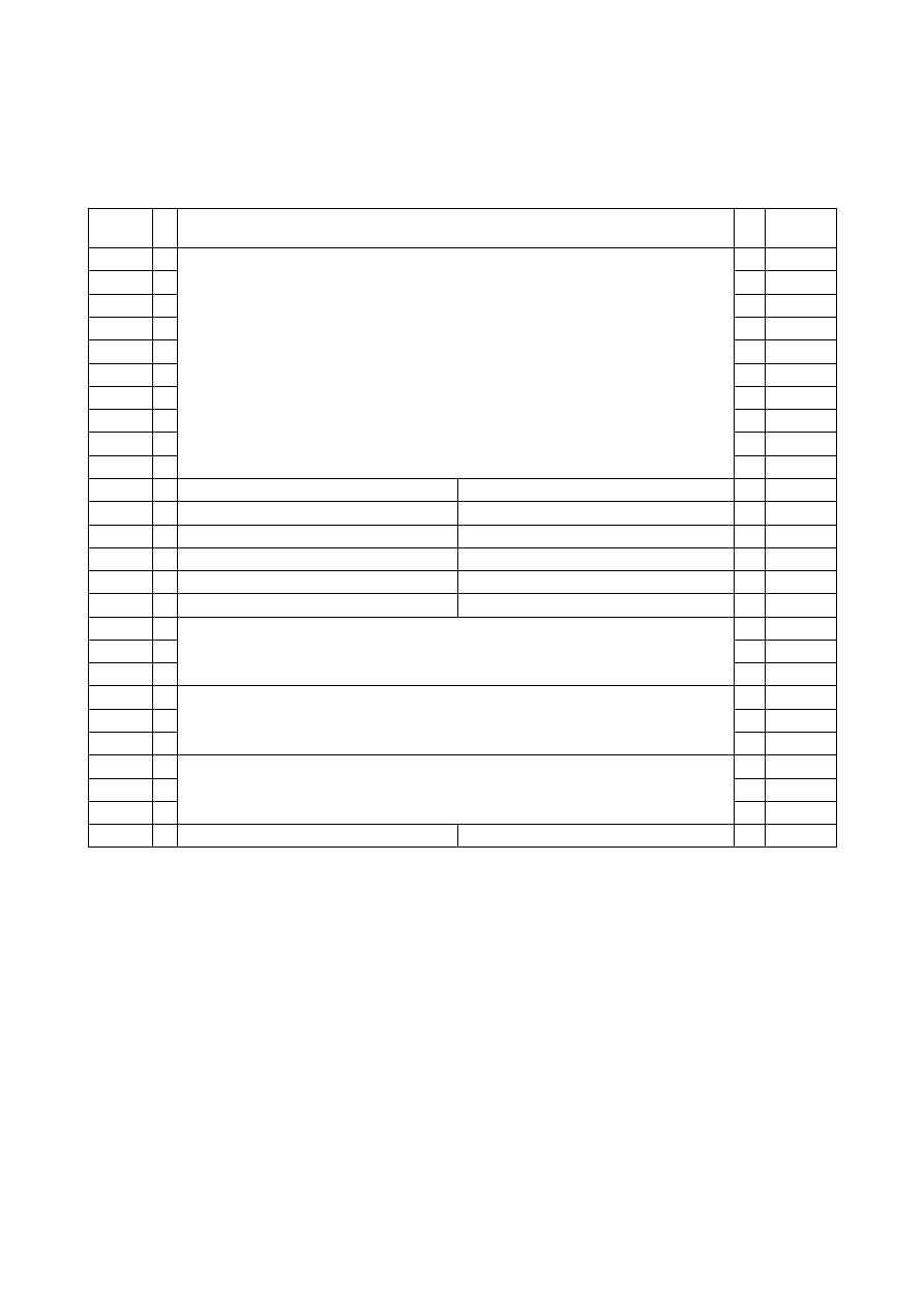
Upper
Row
Of
Pins
Signal
Voltage
Remarks
Lower
Row
Of
Pins
Signal
Voltage
Remarks
1
SYNC-
XY3-100-
compatible signals
2
SYNC+
XY3-100-
compatible signals
3
CLK-
4
CLK+
5
X-
6
X+
7
Y-
8
Y+
9
10
11
BACK-
12
BACK+
13
14
15
16
17
+V
+15..24V
Power supply from
scanner card
18
+V
+15..24V
Power supply from
scanner card
19
+V
+15..24V
20
GND
GND
21
GND
GND
22
GND
GND
23
-V
-15..24V
24
-V
-15..24V
25
-V
-15..24V
26
When the HALdrive is used together with the E1803D scanner controller card, a direct 1:1 connection can be
established between the 26 pin scanner signal connector of the E1803D controller and this connector. Then
power has to be supplied via the three screw-connectors of the E1803D (for details please refer to manual of
E1803D scanner controller card
For all other scanner controller cards, wring has to be done according to their pinout. For further information
7
please refer to appendices below.
5.2 Galvo X and Y Signals
A standard 6 pin 2,54 mm header, to be used with an IDC connector:
Pin Signal
Description
1
NC
Unused and reserved for future use, do not connect!
2
NC
Unused and reserved for future use, do not connect!
3
Galvo-Y analogue output with voltage possible in range +-5V..+-10V
4
Galvo-X analogue output with voltage possible in range +-5V..+-10V
5
GND
Common ground for Galvo-X
6
GND
Common ground for Galvo-Y
Pins 3 and 4 typically work in range -5V..+5V. For the +-10V hardware variant the Pins 3 and 4 work in range -
10V..+10V. Pins 5 and 6 is connected to GND.
The maximum current to be pulled out of each of the outputs should never exceed 20 mA. Lower currents are
recommended to avoid unnecessary heating of the whole board.
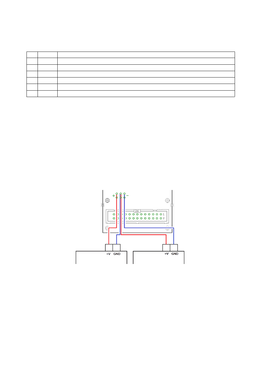
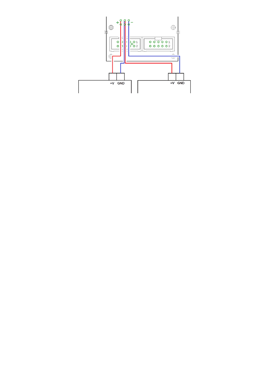
5.3 Optional Power Supply Input
These are optional separate power supply input pins which can be used when power is not or can not provided
via connector (1). Here a symmetric voltage in range +-15V..+-24V can be fed in. The two outer pins marked
with “-” are for -15V..-24V, the two middle pins are for GND and the two other outer pins marked with “+” are for
+15V..+24V power input.
When no power supply with symmetric/bipolar outputs is available, it is possible to combine two standard
power supplies, here GND of the first power supply has to be connected with +V of the second power supply
and with the GND-pins of the HALdrive:
8

5.4 Initial Operation
After the HALdrive does not have a nameable boot-up time, putting it into operation consists of a few steps
only:
1. power up HALdrive and if necessary the connected scanner controller card
2. power-up connected galvo drivers (can be done together with powering the HALdrive)
3. start sending data from the scanner controller card to the HALdrive board
For security reasons it is recommended to not to send any data to the HALdrive while it is still turned off, so
that it may start up in the middle of an already running data transmission. This may lead to a situation where the
first valid position command received is at an extreme and unexpected position causing damage to the
connected scanhead as it jumps to this extreme position too fast.
For the same reason also the galvo driver should be powered and be ready to use before the scanner controller
sends any data, elsewhere when the connected galvos jump to an extreme position immediately, this may cause
damage to the galvos and/or mirrors.
9
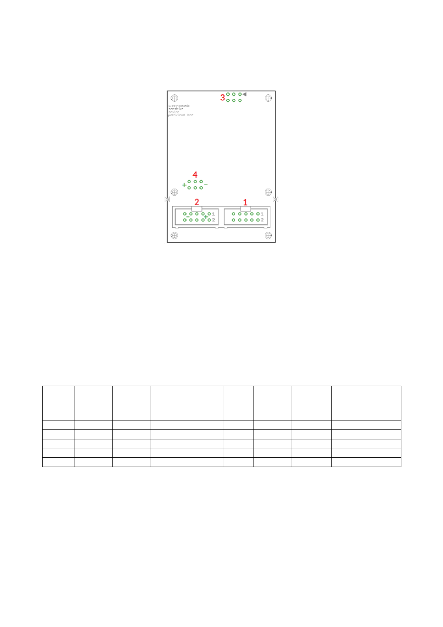
6 HALdrive N20 Board And Connectors
The NX-02 board variant provides the following connectors:
1. NX-02 interface for scanner input signals (as described below), this connector can be used together
with a single 26 pin plug that covers both, connectors (1) and (2) at the same time
2. Main power interface for power input, this connector can be used together with a single 26 pin plug
that covers both, connectors (1) and (2) at the same time
3. 2,54mm 6pin connector for Galvo-X and Galvo Y analogue output signals and Galvo X and Galvo Y
analogue feedback signals (optional)
4. Optional separate power supply input pin, when not already provided via connector (2)
6.1 Scanner Signals
Upper
Row
Of
Pins
Signal
Voltage
Remarks
Lower
Row
Of
Pins
Signal
Voltage
Remarks
1
DATA+
NX-02 signal
2
DATA-
NX-02 signal
3
4
5
6
7
8
BACK-
NX-02 signal
9
BACK+
NX-02 signal
10
The board accepts 2D and 3D input data.
10
6.2 Power Supply
Upper
Row
Of
Pins
Signal
Voltage
Remarks
Lower
Row
Of
Pins
Signal
Voltage
Remarks
1
+V
+15..24V
Power supply from
scanner card
2
+V
+15..24V
Power supply from
scanner card
3
+V
+15..24V
4
GND
GND
5
GND
GND
6
GND
GND
7
-V
-15..24V
8
-V
-15..24V
9
-V
-15..24V
10
6.3 Galvo X and Y Signals
A standard 6 pin 2,54 mm header, to be used with an IDC connector:
Pin Signal
Description
1
FeedbackY analogue input for current galvo position
2
FeedbackX analogue input for current galvo position
3
Galvo-Y
analogue output with voltage possible in range +-5V..+-10V
4
Galvo-X
analogue output with voltage possible in range +-5V..+-10V
5
GND
Common ground for Galvo-X
6
GND
Common ground for Galvo-Y
The galvo signal output pins 3 and 4 typically work in range -5V..+5V. For the +-10V hardware variant the Pins 3
and 4 work in range -10V..+10V. Pins 5 and 6 are connected to GND.
The maximum current to be pulled out of each of the outputs should never exceed 20 mA. Lower currents are
recommended to avoid unnecessary heating of the whole board.
Pins 1 and 2 can be used to feed in a -5V..+5V analogue signal which corresponds to the actual galvo position.
This value is converted to a NX-02 feedback signal which reports the current galvo position and movement
back to the scanner controller card. Here the feedback voltage has to correspond to the input
positions/command voltage for the galvo:
•
minimum position / nominal galvo voltage of -5V/-10V has to correspond to an actual input voltage
close to -5V
•
central position / nominal galvo voltage of 0V has to correspond to an actual input voltage close to 0V
•
maximum position / nominal galvo voltage of 5V/10V has to correspond to an actual input voltage close
to +5V
6.4 Optional Power Supply Input
These are optional separate power supply input pins which can be used when power is not or can not provided
via connector (2). Here a symmetric voltage in range +-15V..+-24V can be fed in. The two outer pins marked
with “-” are for -15V..-24V, the two middle pins are for GND and the two other outer pins marked with “+” are for
+15V..+24V power input.
When no power supply with symmetric/bipolar outputs is available, it is possible to combine two standard
power supplies, here GND of the first power supply has to be connected with +V of the second power supply
and with the GND-pins of the HALdrive:
11
12

6.5 Initial Operation
Putting the N20 board into operation consists of a few steps only:
1. power-up connected galvo drivers
2. power up the board and if necessary the connected scanner controller card (can be done together with
powering the galvo drivers)
3. wait until the calibration sequence has been completed: here the board performs a movement with
both mirrors to the outer position (+5V / +10V) and then moves back to the centre position (0V);
during this time the analogue feedback channels (if used) are measured and calibrated
4. start sending data from the scanner controller card to the board
For security reasons it is recommended to not to send any data to the board while it is still turned off, so that it
may start up in the middle of an already running data transmission. This may lead to a situation where the first
valid position command received is at an extreme and unexpected position causing damage to the connected
scanhead as it jumps to this extreme position too fast.
For the same reason also the galvo driver should be powered and be ready to use before the scanner controller
sends any data, elsewhere when the connected galvos jump to an extreme position immediately, this may cause
damage to the galvos and/or mirrors.
13
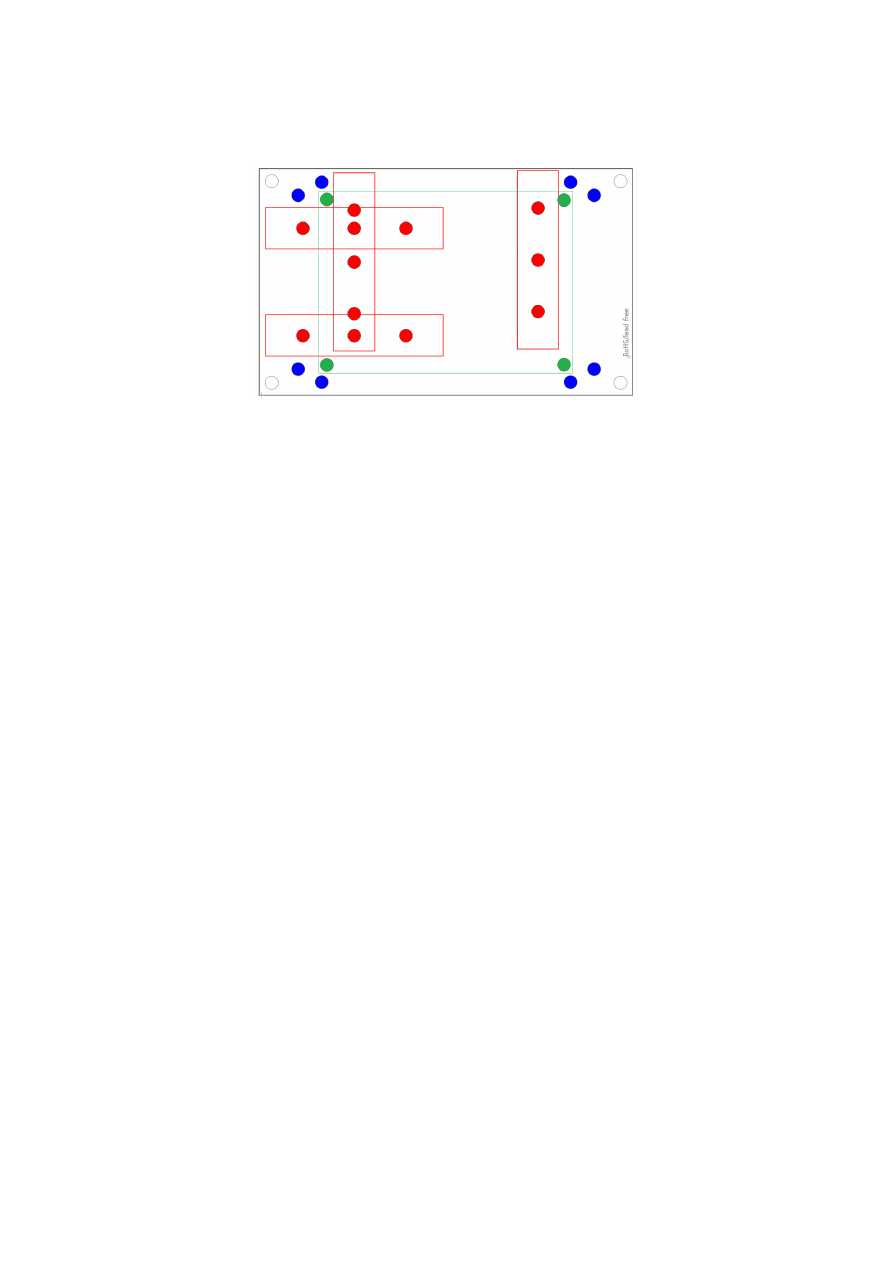
7 E170Xbase
The E170Xbase extension is a mounting help for easy installation on DIN rails/C45 rails and other possibilities
of mechanical integration into machines:
RED
– mounting positions for DIN/C45 rail locks/DIN/C45 rail adapters (bottom side). Pairs of locks can be
mounted in one of 2 possible orientations. Here locks of type Phoenix Contact 1201578 or similar can be used.
With these locks the board then can be clamped on a DIN/C45 rail.
BLUE
– optional; mounting holes for a E170X scanner controller card on top of the E170Xbase in one of two
possible orientations. These holes are symmetrically arranged so that the board can be mounted by 180
degrees rotated. Here Hex stands/distance bolts with M3 threads (or similar) can be screwed in where the
controller card is mounted on top.
GREEN
– mounting holes for a HALdrive converter board (top side), here Hex stands/distance bolts with M2
threads (or similar) can be screwed in where the HALdrive is mounted on top.
Mounting procedure for E170Xbase:
1. Identify suitable positions (
RED
) for two DIN/C45 rail locks and mount them on bottom side (two or
three screws from top side into the lock on bottom)
2. Mount hex-stands or distance bolts in at least four of the given mounting holes (
GREEN
).
3. Mount HALdrive on top of these hex-stands/distance bolts
4. Clamp the board on your DIN/C45 rail
14
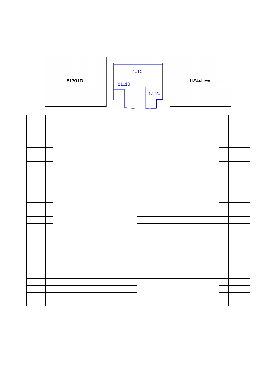
APPENDIX A – Wiring between HALdrive X20 and E1701D
To connect an E1701D scanner controller card with the HALdrive X20, a split cable is needed between the
white laser/scanner interface connector of E1701D and the 26-pin connector of the HALdrive X20 board:
E1701D
pin
Description of signals
from E1701D
Description of signals
to HALdrive
HALdrive
pin
1
-
XY3-100 signal lines
- 1
2
-
- 2
3
-
- 3
4
-
- 4
5
-
- 5
6
-
- 6
7
-
- 7
8
-
- 8
9
-
- 9
10
-
- 10
11
o
Laser and control signals
Back-channel, optionally connect with
pins 25/26 of E1701D
- 11
12
o
- 12
13
o
X 13
14
o
X 14
15
o
X 15
16
o
X 16
17
o
+15..+24V (from power supply)
o 17
18
o
o 18
19
X
o 19
20
X
GND (from power supply)
o 20
21
X
o 21
22
X
o 22
23
X
-15..-24V (from power supply)
o 23
24
X
o 24
25
- Back-channel, optionally connect with
F-/F+ of HALdrive
o 25
26
-
X 26
“-” – connection to be established between E1701D and HALdrive
“o” – connection to external equipment but not between E1701D and HALdrive
“X” – no connection allowed here
15
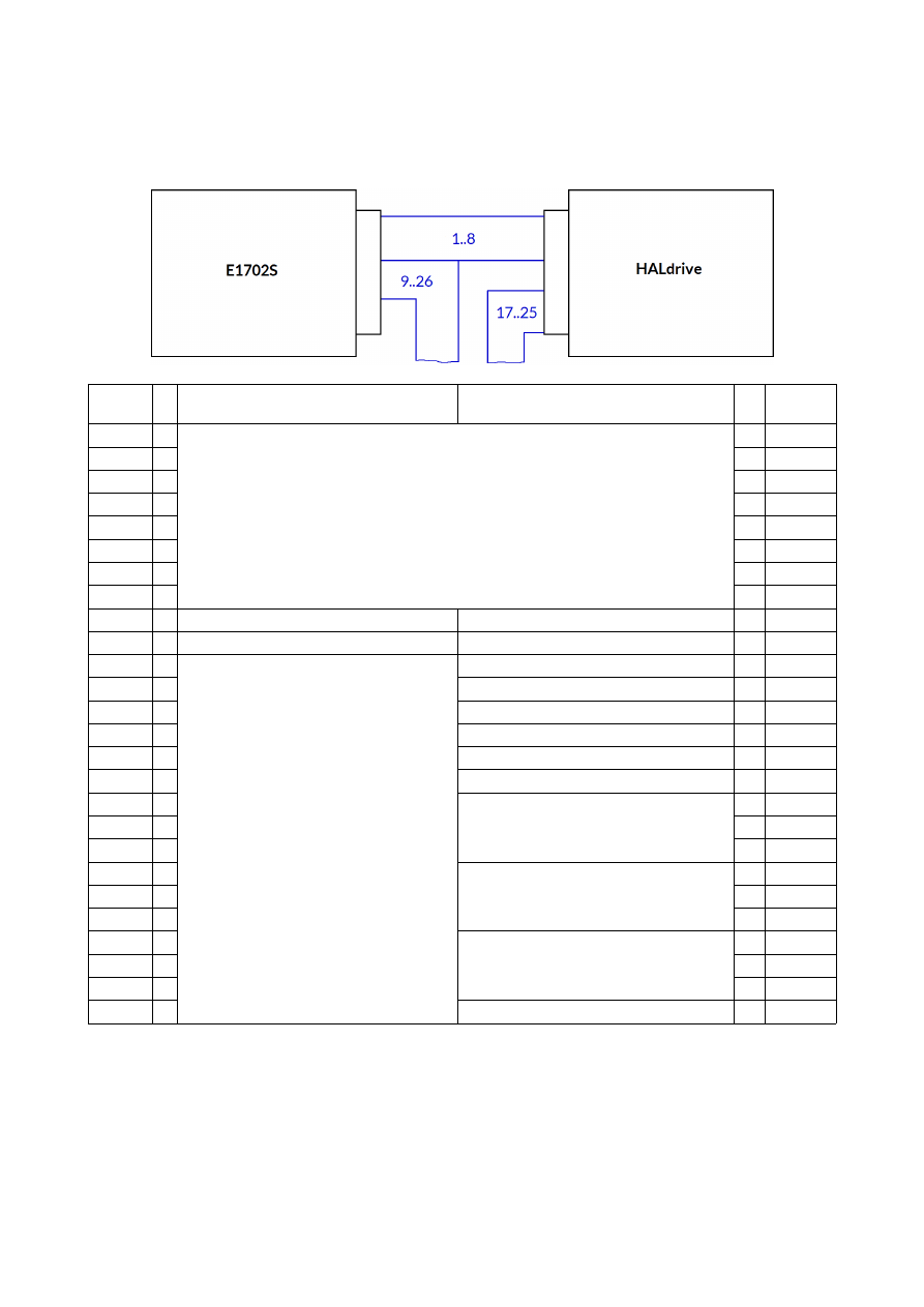
APPENDIX B – Wiring between HALdrive X20 and E1702S
To connect an E1702S scanner controller card with the HALdrive X20, a split cable is needed between the
white laser/scanner interface connector of E1702S and the 26-pin connector of the HALdrive X20 board:
E1702S
pin
Description of signals
from E1701D
Description of signals
to HALdrive
HALdrive
pin
1
-
XY3-100 signal lines
- 1
2
-
- 2
3
-
- 3
4
-
- 4
5
-
- 5
6
-
- 6
7
-
- 7
8
-
- 8
9
o
X 9
10
o
X 10
11
o
Laser and control signals
X 11
12
o
X 12
13
o
X 13
14
o
X 14
15
o
X 15
16
o
X 16
17
o
+15..+24V (from power supply)
o 17
18
o
o 18
19
o
o 19
20
o
GND (from power supply)
o 20
21
o
o 21
22
o
o 22
23
o
-15..-24V (from power supply)
o 23
24
o
o 24
25
o
o 25
26
o
X 26
“-” – connection to be established between E1702S and HALdrive X20
“o” – connection to external equipment such as Laser but not between E1702S and HALdrive X20
“X” – no connection allowed here
16
APPENDIX C – Wiring between HALdrive X20 and E1803D
For connection between E1803D and HALdrive X20 a simple 1:1 wire is needed between the 26-pin IDC
connector of the E1803D and the (optionally white) IDC connector of the HALdrive X20 board.
E1803D
pin
Description
HALdrive
pin
1
-
XY3-100 signal lines
- 1
2
-
- 2
3
-
- 3
4
-
- 4
5
-
- 5
6
-
- 6
7
-
- 7
8
-
- 8
9
-
- 9
10
-
- 10
11
O
O 11
12
O
O 12
13
O
O 13
14
O
O 14
15
O
O 15
16
O
O 16
17
-
+15V..+24V (via E1803D screw terminal)
- 17
18
-
- 18
19
-
- 19
20
-
GND (via E1803D screw terminal)
- 20
21
-
- 21
22
-
- 22
23
-
-15V..-24V (via E1803D screw terminal)
- 23
24
-
- 24
25
-
- 25
26
O
O 26
“-” connection to be established between E1803D and HALdrive X20
“O” currently unused signal but can be connected
17
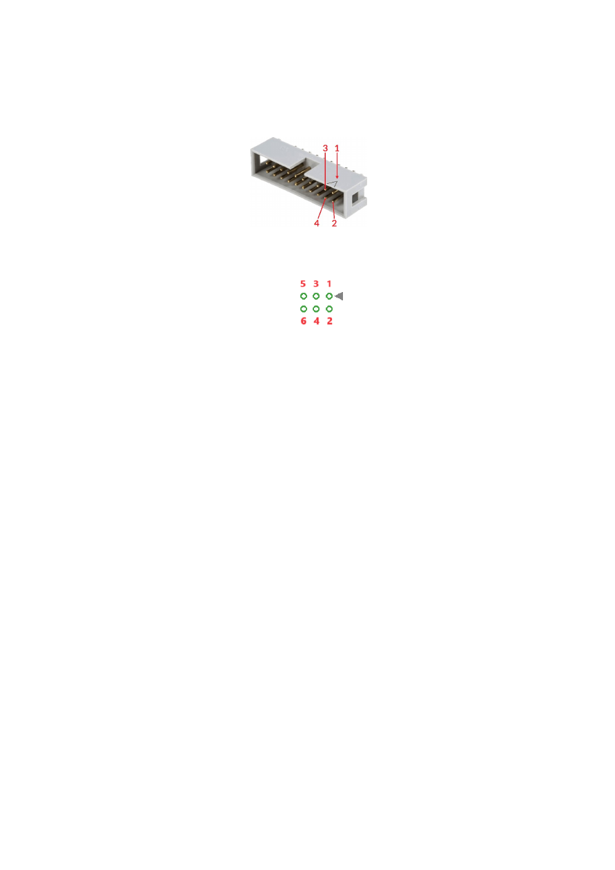
APPENDIX D – IDC connector pin numbering
Pin numbering of the, 2,54 mm 26 pin IDC connector (according to pinout-tables shown in hardware
description sections above) can be seen in below’s images:
IDC-connector socket, side view
IDC-connector socket, top view on PCB mounting side
Pin 1 is marked by a small arrow either on the connector itself or directly on the PCB. Second pin is located
below of it, counting continues column-wise.
18

APPENDIX E – XY3-100 protocol description
For details about the XY3-100 protocol, please refer to
https://lasia.org/documents.php
19
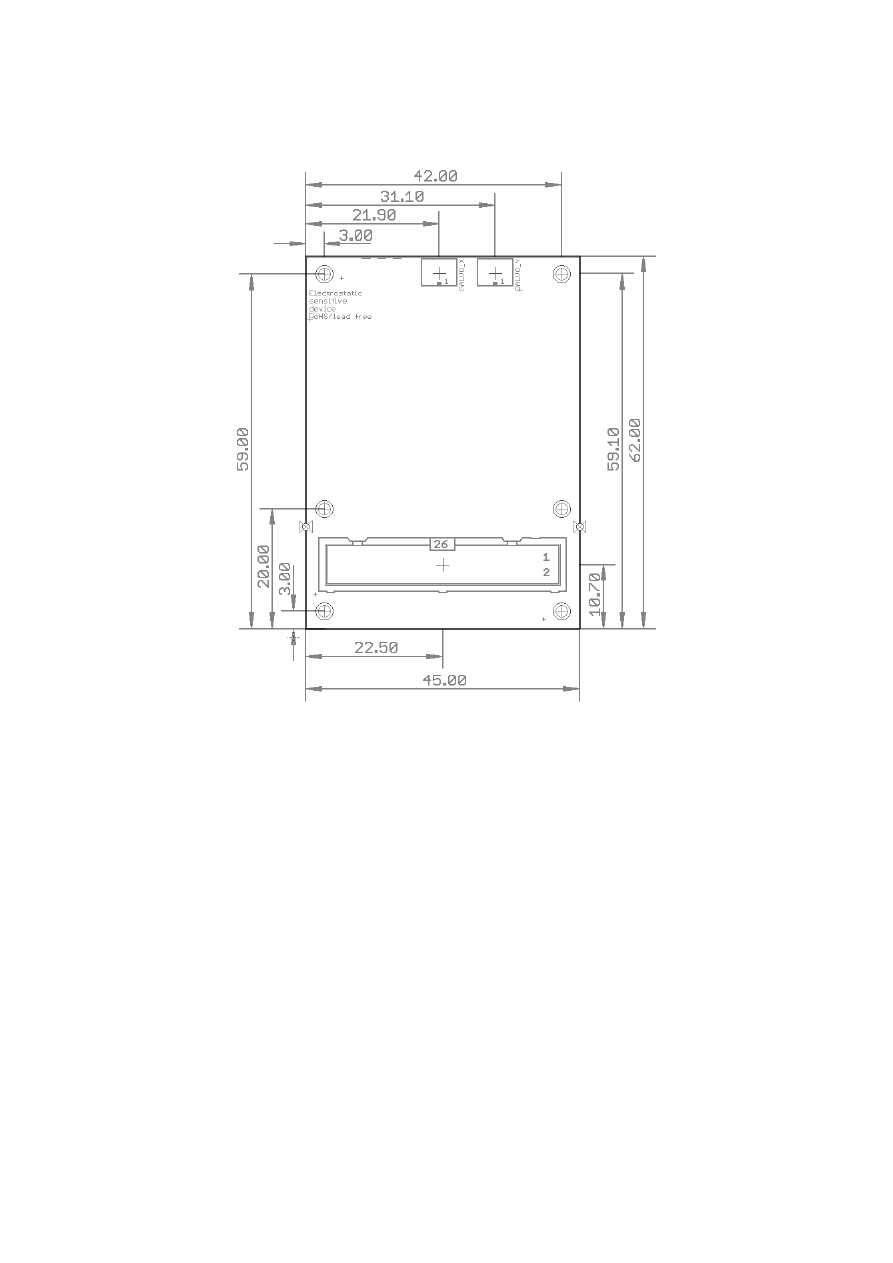
APPENDIX F – Board dimensions
Board dimension drawing, all values are given in unit mm.
The six holes at the outer corners/edges have a diameter of 2,8 mm each.
20

Alphabetical Index
C
C45 rail...............................................................................................................................................................................................................14
C45 rail adapter..............................................................................................................................................................................................14
C45 rail lock......................................................................................................................................................................................................14
D
dimension drawing........................................................................................................................................................................................20
dimensions........................................................................................................................................................................................................20
DIN rail...............................................................................................................................................................................................................14
DIN/C45 rail adapter....................................................................................................................................................................................14
DIN/C45 rail lock...........................................................................................................................................................................................14
E
E1701D..............................................................................................................................................................................................................15
E1702S...............................................................................................................................................................................................................16
E1803D..............................................................................................................................................................................................................17
electrostatic sensitive device......................................................................................................................................................................5
ESD.........................................................................................................................................................................................................................5
F
Feedback...........................................................................................................................................................................................................11
G
Galvo...............................................................................................................................................................................................................7, 10
I
IDC connector.................................................................................................................................................................................................18
N
NX-02...........................................................................................................................................................................................................6, 10f.
P
Power supply...............................................................................................................................................................................................7, 11
X
XY3-100......................................................................................................................................................................................................6f., 19
21