
E1701 Modular Scanner Controller
Users Manual
© 2014-2026 by HALaser Systems GmbH
1
E1701 Modular Scanner Controller
Users Manual
© 2014-2026 by HALaser Systems GmbH
1

Table of Contents
1 Copyright.........................................................................................................................................................................................................4
2 History..............................................................................................................................................................................................................7
3 Safety................................................................................................................................................................................................................9
4 Overview......................................................................................................................................................................................................10
4.1.1 E1701D XY2-100/XY3-100 Digital Laser Scanner Controller Baseboard.................................................10
4.1.2 E1701A Analogue Laser Scanner Controller Baseboard....................................................................................11
4.1.3 E1701 LP8 Extension Board............................................................................................................................................11
4.1.4 E1701 Digi I/O Extension Board....................................................................................................................................11
4.1.5 E1701 Secondary Head Extension Board..................................................................................................................12
5 Position Within The System..................................................................................................................................................................13
6 Boards And Connectors.........................................................................................................................................................................14
6.1.1.1 Ethernet Configuration With Windows 10..............................................................................................15
6.1.1.2 Ethernet Configuration With Windows 11..............................................................................................15
6.1.1.3 Ethernet Configuration With Linux.............................................................................................................16
6.1.2 USB.............................................................................................................................................................................................17
6.1.3 Power........................................................................................................................................................................................17
6.1.4 Power LED...............................................................................................................................................................................18
6.1.5 User LEDs................................................................................................................................................................................18
6.1.6 Laser LED.................................................................................................................................................................................19
6.1.7 Reset-Button..........................................................................................................................................................................19
6.1.8 microSD-Card........................................................................................................................................................................19
6.1.9.1 XY2-100 Connection Cable............................................................................................................................27
6.1.9.2 XY3-100 Connection Cable............................................................................................................................28
6.1.10 Extension Connectors.....................................................................................................................................................29
6.1.11 Stand-Alone Operation...................................................................................................................................................30
6.1.11.1 Create Stand-Alone Data with BeamConstruct..................................................................................30
6.1.11.2 Stand-Alone Configuration Parameters.................................................................................................32
6.1.11.3 Stand-Alone Control.......................................................................................................................................34
6.2.1 Ethernet...................................................................................................................................................................................35
6.2.2 USB.............................................................................................................................................................................................35
6.2.3 Power........................................................................................................................................................................................36
6.2.4 Power LED...............................................................................................................................................................................36
6.2.5 User LEDs................................................................................................................................................................................36
6.2.6 Laser LED.................................................................................................................................................................................37
6.2.7 microSD-Card........................................................................................................................................................................37
6.2.8 Laser/Scanner Signals........................................................................................................................................................37
6.2.9 Extension Connectors........................................................................................................................................................38
6.2.10 DAC Heatsinks...................................................................................................................................................................38
6.2.11 Stand-Alone Operation...................................................................................................................................................38
6.3.1 MO LED....................................................................................................................................................................................39
6.3.2 Laser Signals...........................................................................................................................................................................39
6.3.3 Extension Connectors........................................................................................................................................................40
6.5.1 Scanner Signals......................................................................................................................................................................45
6.5.2 Extension Connectors........................................................................................................................................................47
2

6.6.1 E1701dock Connectors.....................................................................................................................................................48
6.6.2 E1701dock Wiring...............................................................................................................................................................52
7 Quick Start into E1701A/D...................................................................................................................................................................55
8 Command Interface.................................................................................................................................................................................56
8.1 General Commands.......................................................................................................................................................................56
8.2 Stand-Alone Control Commands.............................................................................................................................................57
8.3 Hardware Commands...................................................................................................................................................................64
8.4 Mark Control Commands............................................................................................................................................................64
9.1.2 Error Codes..........................................................................................................................................................................101
9.1.3 Compatibility.......................................................................................................................................................................102
9.2 RTC4 Compatibility Functions...............................................................................................................................................102
9.3 USC1/2 Compatibility Functions (SCI interface)............................................................................................................105
9.4 OLSC Compatibility Functions (Open Laser Show Controller interface).............................................................107
Wiring between IPG YLP Series Type B, B1 and B2, GZTech YFPN series fiber laser.............................................108
Wiring between E1701 and JPT YDFLP series fiber laser (“MOPA”) or IPG YLP Series Type D fiber laser or
Raycus RFL PMX/PQB Series fiber laser....................................................................................................................................109
Wiring between E1701 and IPG YLP Series Type E fiber laser.........................................................................................110
Wiring between E1701 and IPG YLP Series Type F fiber laser.........................................................................................111
Wiring between E1701 and IPG YLR Series laser..................................................................................................................112
Wiring between E1701 and SPI G4 Pulsed Fibre Laser / TRUMPF TruPulse nano series....................................113
Wiring between E1701 and Raycus fiber laser........................................................................................................................115
Wiring between E1701 and MaxPhotonics MFP fiber laser..............................................................................................116
Wiring between E1701 and DAVI D-Series RF CO
APPENDIX B – IDC connector pin numbering...............................................................................................................................119
APPENDIX C – E1701D XY2-100 protocol description............................................................................................................120
APPENDIX D – E1701D XY3-100 protocol description............................................................................................................121
APPENDIX E – E1701D SL2-100 protocol description..............................................................................................................122
APPENDIX F – E1701D RL3-100 protocol description.............................................................................................................123
APPENDIX G – Board dimensions.......................................................................................................................................................124
3

1 Copyright
This document is © by HALaser Systems.
E1701 base- and extension boards, their hardware and design are copyright / trademark / legal trademark of
HALaser Systems.
IPG and others are copyright / trademark / legal trademark of IPG Laser GmbH / IPG Photonics Corporation.
Scanlab, RTC4, RTC5, SL2-100 and others are copyright / trademark / legal trademark of Scanlab AG.
SCAPS, USC1, USC2 and others are copyright / trademark / legal trademark of SCAPS GmbH.
Raylase, SP-ICE, RL3-100 and others are copyright / trademark / legal trademark of Raylase AG.
Rofin, Rofin-Sinar, Visual Laser Marker and others are copyright / trademark / legal trademark of Raylase AG.
Sunny, CSC-USB and others are copyright / trademark / legal trademark of Beijing Century Sunny Technology
CO., LTD
CTI, Cambridge Technology, Novanta and others are copyright / trademark / legal trademark of Novanta Inc.
Han’s, Han’s Laser and others are copyright / trademark / legal trademark of Han’s Laser Technology Industry
Group Co., Ltd.
All other names / trademarks are copyright / trademark / legal trademark of their respective owners.
Portions of the E1701 firmware are based on lwIP 1.4.0 (or newer):
Copyright (c) 2001, 2002 Swedish Institute of Computer Science.
All rights reserved.
Redistribution and use in source and binary forms, with or without modification, are permitted provided that
the following conditions are met:
1.Redistributions of source code must retain the above copyright notice, this list of conditions and the following
disclaimer.
2.Redistributions in binary form must reproduce the above copyright notice, this list of conditions and the
following disclaimer in the documentation and/or other materials provided with the distribution.
3.The name of the author may not be used to endorse or promote products derived from this software without
specific prior written permission.
THIS SOFTWARE IS PROVIDED BY THE AUTHOR ``AS IS'' AND ANY EXPRESS OR IMPLIED WARRANTIES,
INCLUDING, BUT NOT LIMITED TO, THE IMPLIED WARRANTIES OF MERCHANTABILITY AND FITNESS
FOR A PARTICULAR PURPOSE ARE DISCLAIMED. IN NO EVENT SHALL THE AUTHOR BE LIABLE FOR ANY
DIRECT, INDIRECT, INCIDENTAL, SPECIAL, EXEMPLARY, OR CONSEQUENTIAL DAMAGES (INCLUDING,
BUT NOT LIMITED TO, PROCUREMENT
OF SUBSTITUTE GOODS OR SERVICES; LOSS OF USE, DATA, OR PROFITS; OR BUSINESS
INTERRUPTION) HOWEVER CAUSED AND ON ANY THEORY OF LIABILITY, WHETHER IN CONTRACT,
STRICT LIABILITY, OR TORT (INCLUDING NEGLIGENCE OR OTHERWISE) ARISING IN ANY WAY OUT OF
THE USE OF THIS SOFTWARE, EVEN IF ADVISED OF THE POSSIBILITY
OF SUCH DAMAGE.
Portions of the E1701 firmware are based on FatFS R0.10a (or newer):
FatFs module is an open source software to implement FAT file system to small embedded systems. This is a
free software and is opened for education, research and commercial developments under license policy of
following terms.
4

Copyright (C) 2014, ChaN, all right reserved.
The FatFs module is a free software and there is NO WARRANTY.
No restriction on use. You can use, modify and redistribute it for personal, non-profit or commercial product
UNDER YOUR RESPONSIBILITY.
Redistributions of source code must retain the above copyright notice.
Portions of the E1701 firmware are based on StarterWare 2.0 (or newer):
Copyright (C) 2010 Texas Instruments Incorporated - http://www.ti.com/
Redistribution and use in source and binary forms, with or without
modification, are permitted provided that the following conditions are met:
Redistributions of source code must retain the above copyright notice, this list of conditions and the following
disclaimer.
Redistributions in binary form must reproduce the above copyright notice, this list of conditions and the
following disclaimer in the documentation and/or other materials provided with the distribution.
Neither the name of Texas Instruments Incorporated nor the names of its contributors may be used to endorse
or promote products derived from this software without specific prior written permission.
THIS SOFTWARE IS PROVIDED BY THE COPYRIGHT HOLDERS AND CONTRIBUTORS "AS IS" AND ANY
EXPRESS OR IMPLIED WARRANTIES, INCLUDING, BUT NOT LIMITED TO, THE IMPLIED WARRANTIES OF
MERCHANTABILITY AND FITNESS FOR A PARTICULAR PURPOSE ARE DISCLAIMED. IN NO EVENT SHALL
THE COPYRIGHT OWNER OR CONTRIBUTORS BE LIABLE FOR ANY DIRECT, INDIRECT, INCIDENTAL,
SPECIAL, EXEMPLARY, OR CONSEQUENTIAL DAMAGES (INCLUDING, BUT NOT LIMITED TO,
PROCUREMENT OF SUBSTITUTE GOODS OR SERVICES; LOSS OF USE, DATA, OR PROFITS; OR BUSINESS
INTERRUPTION) HOWEVER CAUSED AND ON ANY THEORY OF LIABILITY, WHETHER IN CONTRACT,
STRICT LIABILITY, OR TORT (INCLUDING NEGLIGENCE OR OTHERWISE) ARISING IN ANY WAY OUT OF
THE USE OF THIS SOFTWARE, EVEN IF ADVISED OF THE POSSIBILITY OF SUCH DAMAGE.
Copyright (c) 2008-2010 Texas Instruments Incorporated. All rights reserved.
Software License Agreement
Texas Instruments (TI) is supplying this software for use solely and exclusively on TI's microcontroller products.
The software is owned by TI and/or its suppliers, and is protected under applicable copyright laws. You may not
combine this software with "viral" open-source software in order to form a larger program.
THIS SOFTWARE IS PROVIDED "AS IS" AND WITH ALL FAULTS. NO WARRANTIES, WHETHER EXPRESS,
IMPLIED OR STATUTORY, INCLUDING, BUT NOT LIMITED TO, IMPLIED WARRANTIES OF
MERCHANTABILITY AND FITNESS FOR A PARTICULAR PURPOSE APPLY TO THIS SOFTWARE. TI SHALL
NOT, UNDER ANY CIRCUMSTANCES, BE LIABLE FOR SPECIAL, INCIDENTAL, OR CONSEQUENTIAL
DAMAGES, FOR ANY REASON WHATSOEVER.
This is part of AM1808 Sitaraware USB Library and reused from revision 6288 of the Stellaris USB Library.
Portions of the E1701 firmware are based on libzint-backend 2.0 (or newer):
libzint - the open source barcode library, Copyright (C) 2008-2017 Robin Stuart <rstuart114@gmail.com>
Redistribution and use in source and binary forms, with or without modification, are permitted provided that
the following conditions are met:
1. Redistributions of source code must retain the above copyright notice, this list of conditions and the
following disclaimer.
2. Redistributions in binary form must reproduce the above copyright notice, this list of conditions and
the following disclaimer in the documentation and/or other materials provided with the distribution.
5

3. Neither the name of the project nor the names of its contributors may be used to endorse or promote
products derived from this software without specific prior written permission.
THIS SOFTWARE IS PROVIDED BY THE COPYRIGHT HOLDERS AND CONTRIBUTORS "AS IS" AND ANY
EXPRESS OR IMPLIED WARRANTIES, INCLUDING, BUT NOT LIMITED TO, THE IMPLIED WARRANTIES OF
MERCHANTABILITY AND FITNESS FOR A PARTICULAR PURPOSE ARE DISCLAIMED. IN NO EVENT SHALL
THE COPYRIGHT OWNER OR CONTRIBUTORS BE LIABLE FOR ANY DIRECT, INDIRECT, INCIDENTAL,
SPECIAL, EXEMPLARY, OR CONSEQUENTIAL DAMAGES (INCLUDING, BUT NOT LIMITED TO,
PROCUREMENT OF SUBSTITUTE GOODS OR SERVICES; LOSS OF USE, DATA, OR PROFITS; OR BUSINESS
INTERRUPTION) HOWEVER CAUSED AND ON ANY THEORY OF LIABILITY, WHETHER IN CONTRACT,
STRICT LIABILITY, OR TORT (INCLUDING NEGLIGENCE OR OTHERWISE) ARISING IN ANY WAY OUT OF
THE USE OF THIS SOFTWARE, EVEN IF ADVISED OF THE POSSIBILITY OF SUCH DAMAGE.
6

2 History
Date
Changes in document
05/2026
Description of
csao0
command added
09/2025
Wiring/configuration description for GZTECH DPSS UV laser added
06/2024
Description of limitations of dynamic texts clarified
06/2024
Description of parameter “
iothres
” clarified
03/2024
Added parameter and command
cswaf
01/2024
Description of E1701dock extended
11/2023
Added description of new function
E170X_set_signal_point()
10/2023
Windows 11 Ethernet configuration description added
07/2023
Reference to header files and programming examples added
05/2023
HALdrive mounting position added to E170Xbase description
03/2023
Behaviour of Alive-LED clarified
12/2022
Command
cdepr
added
12/2022
Description of
E170X_stop_execution()
and
cvers
extended
12/2022
Missing description of flags
E170X_PIXELMODE_
added
11/2022
Added new function
E170X_get_pos()
11/2022
New function names
E170X_
used in API description
10/2022
Added new stand-alone commands
cspof
,
cfror
and
cpuor
10/2022
Electrical behaviour of digital IOs clarified
06/2022
New commands
cslp8
,
cslgt
and
cslmo
added
02/2022
Tune-flag added to invert input logic of ExtStart input
02/2022
Tune-flag now also can read hex-values with 0x prefix
02/2022
Added tune-flags to invert LP8 and MO outputs
12/2021
New configuration parameter
lasergate
11/2021
Tune-flag 524288 added
10/2021
Function
E1701_set_overspeed()
added
10/2021
Pinout description of E1701dock extended
08/2021
New parameters
tunereadyout
and
tunemarkout
added
07/2021
Inappropriate language and naming removed (“master”, “slave”, ...)
07/2021
E1701dock pinout clarified/description extended
07/2021
Added description of
ctlxy
command
07/2021
Wiring of JPT/MOPA laser with pulse width serial interface clarified
07/2021
Description of CSV-support in stand-alone mode added
05/2021
E1701dock description
04/2021
New “d”-command 0x18 / delay and 0x19 / LP8 Latch added
04/2021
Description of new configuration parameter “eth=2” for Ethernet interface polling added
04/2021
Description of Ethernet configuration updated for Windows 10
03/2021
Added function
E1701_get_serial_number()
12/2020
Added commands “
cgmtx
” and “
csmtx
”
12/2020
Added new stand-alone function and configuration parameters “
iolatch
” and “
iothres
”
09/2020
Added schematics for E1701A power supply connection
07/2020
Added descriptions for XY3-100 interfaces
01/2020
Added description of commands „
csbuf
“ and „
cgbuf
“
01/2020
Added new stand-alone mode „
idxselect
“
10/2019
Function description of
E1701_set_standby2()
added
10/2019
Wiring scheme for MaxPhotonics fiber laser added
10/2019
Example in description of
pethd
-parameter corrected
07/2019
Extended description of card state flags
02/2019
Added “
pethd
” configuration parameter
12/2018
Added “
haltedloopbuffer
” configuration parameter
10/2018
Added commands
cscor
and
cgcor
10/2018
Added “
haltedlooptimeout
” configuration parameter
09/2018
New tune-flag added
7

06/2018
Added description of flags of function
E1701_set_xy_correction3()
04/2018
Description of new parameters “digiinit” and “digimask” added
04/2018
Description of new tune-flags added
04/2018
Added description of command
E1701_digi_pulse()
02/2018
New “d”-command 0x45 to download new firmware
12/2017
Added description for matrix-”d”-commands 0x40 and 0x41
10/2017
Added description for
E1701_set_scanner_delays2()
08/2017
Added description for config parameters
wetout
and
mipout
08/2017
Description for
E1701_set_sync()
/
E1701_get_sync()
added
07/2017
Description of USB license retrieval clarified
07/2017
TrueType-support in stand-alone mode
04/2017
Wiring scheme for IPG YLR types added
04/2017
Description of stand-alone programming via API added
04/2017
Pinout for D-SUB15 connector added
03/2017
Added new API function
E1701_set_xy_correction3()
and
E1701_set_matrix2()
02/2017
Images updated
01/2017
Added wiring scheme for IPG type E lasers with APD index mode
01/2017
Added “
iohaltedloop
” stand-alone mode
12/2016
Description of
corrtable0
parameter corrected
11/2016
API function descriptions added and clarified
11/2016
Added “
haltedloop
” stand-alone mode
11/2016
JPT fiber laser wiring scheme added
10/2016
Added new API function
E1701_set_xy_correction2()
10/2016
Added new API function
E1701_set_z_correction()
09/2016
Added description of prebuffering function for ioselect stand-alone mode
08/2016
Board dimension drawings added
06/2016
Added description for second marking on-the-fly encoder input
05/2016
Added standalone commands “cmsor” and “cjsor”
02/2016
Added wiring schematics for Raycus fiber laser
01/2016
Clarified usage of
E1701_release_trigger_point()
01/2016
Added protocol description for E1701D
12/2015
Parameter descriptions for Laser On Delay corrected
10/2015
E1701A specification added
10/2015
Firmware version 21 functions, parameters and commands added
09/2015
Firmware version 20 function descriptions added
09/2015
Error in API description/wobble function corrected
09/2015
Laser wiring description corrected
06/2015
Stand-alone description extended,
E1701_write()
added
04/2015
New I/O and halt- function, new tune parameters
04/2015
SPI G4 wiring schemes extended
03/2015
Description of “d”-commands for sending marking data via USB/Ethernet
02/2015
Pin-out of XY2-100 connector added, SNTP and stand-alone feature description added, ASCII-
command description added
01/2015
Specification of default states of digital outputs added
12/2014
Description for
E1701_mark_pixelline()
added
10/2014
Output current values added, description for Secondary Head Extension added
09/2014
Minor corrections in layout and text
09/2014
Initial version
8

3 Safety
The hardware described within this document is designed to control a laser scanner system. Laser radiation
may effect a person's health or may otherwise cause damage. Prior to installation and operation compliance
with all relevant safety regulations including additional hardware-controlled safety measures has to be
secured. The client shall solely be responsible to strictly comply with all applicable and relevant safety
regulations regarding installation and operation of the system at any time.
Beside of that some laser equipment can be damaged in case it is controlled with wrong signals or signals
outside a given specification. Thus it is highly recommended to check the output generated by this hardware
using e.g. an oscilloscope to avoid problems caused by wrong configurations. This should be done prior to
putting a system into operation for the first time, whenever some parameters have been changed or whenever
any kind of software update was installed.
The hardware described here is shipped without any cover and without prefabricated equipment for electric
installation. It is intended to be integrated in machines or other equipment. It is not a device for use "as is", but a
component which is intended to be used as part of a larger device, e.g. for integration in a machine with own
housing or within an electrical cabinet. Prior to operation compliance with all relevant electric /
electromagnetic safety regulations including additional hardware-controlled safety measures has to be
secured. The client shall solely be responsible to strictly comply with all applicable and relevant regulations
regarding installation and operation of the system at any time.
The hardware described here is an electrostatic sensitive device. This means it can be damaged by common
static charges which build up on people, tools and other non-conductors or semiconductors. To avoid such a
damage, it has to be handled with care and including all relevant procedures (like proper grounding of people
handling the hardware, shielding/covering to not to let a person touch the hardware unwanted, proper
packaging in ESD-bags, ...). For more information please refer to related regulations and standards regarding
handling of ESD devices. The EMC Directive (2014/30/EU) does not apply to this hardware as it is not intended
for an end user (a person without knowledge of EMC) and as it is not otherwise made available on the market.
The Low Voltage Directive (2014/35/EU) does not apply to this hardware as the voltage supply is below the
50V AC / 75V DC limit.
This control board is considered partly completed machinery in accordance with the EU Machinery Directive
(2006/42/EC). It cannot operate independently and is intended to be integrated into a larger machine or
system. The final integrator is responsible for ensuring that the complete machine or system complies with all
applicable safety and regulatory requirements in the intended market (such as CE- certification).
This document describes the E1701-hardware but may contain errors or may be changed without further
notice.
9

4 Overview
This document describes the E1701 modular scanner controller board family, their electrical characteristics
and usage. They consist of E1701D XY2-100/XY3-100 scanner controller baseboard plus optional extension
boards and of E1701A analogue scanner controller baseboard plus optional extension boards. Special variant
E1701M is no scanner controller and therefore not covered by this document.
The E1701 scanner controller boards are designed for controlling galvanometric scanner systems with two or
three axes. Depending on the used extension boards (which are optional) they also supply extensive signals for
laser and external control. The communication between the host system and the controller boards is done via
Ethernet or USB.
When using E1701 scanner controller boards, there is always one baseboard required for proper operation.
This baseboard can be used together with different extension boards that provide additional signals for
controlling the laser marking process. These extension boards are optional and have to be used only in
environments where the additional signals processed by these boards are required. So depending on used type
of laser and requirements, the minimal solution to control a laser marking system may consist of the baseboard
only.
Normally extension boards can be combined with any baseboard and all other extension boards freely, there
are no restrictions for usage. In case some specific extension board types can’t be operated with other boards,
this is stated in description of the related boards below.
Normally an E1701 baseboard can be combined with several extension boards of different types but not with
more than one board of same type. In case of special extension boards where more than one board of the same
type can be used, this is stated in description of the related board below.
4.1 Features
Following the features of available base- and extension boards are described
4.1.1 E1701D XY2-100/XY3-100 Digital Laser Scanner Controller Baseboard
This baseboard can be used to control 2D or 3D scanheads that come with a XY2-100, XY2-100-E or XY3-100
interface. It can be combined with extension boards without any restrictions. E1701D offers following features:
XY2-100 interface to scanhead with X, Y and Z channel
XY2-100-E interface to scanhead with X and Y channel
XY3-100-E interface to scanhead with X and Y channel
100 Mbit Ethernet connection
USB 2.0 connection
online XYZ grid correction with support for several correction table file formats (like SCAPS™ .ucf,
Scanlab™ .ctb and .ct5, Raylase™ .gcd, Rofin™ .fcr, Han’s™ .crt, CTI™ .xml or Sunny™ .txt)
high-definition online XYZ grid correction with BeamConstruct HD correction files (.bco)
fast switching between up to 16 preloaded grid correction tables
10 microseconds vector cycle time and resolution (microstep period)
command execution time down to 0,5 microseconds
realtime processing of laser and scanner signals
26 bit internal resolution (for better quality also with 16 or 18 bit hardware output)
can control nearly every laser type (this may require extension boards as described below)
two laser CMOS digital outputs for usage with YAG, CO2, IPG(tm) and compatible laser types (outputs
can provide PWM frequency, Q-Switch, FPK-pulse, CW/continuously running frequency, stand-by
frequency) running with frequencies of up to 20 MHz
512 MByte DDR3 RAM
1 GHz CPU clock
support for microSD and microSDHC cards
internal command and vector data list with more than 17 million entries
continuous list concept, no need to swap between buffers
BeamConstruct PRO license included
10

open source compatibility library that emulates existing programming interface for fast and easy usage
with existing software (contains e.g. Scanlab(tm) RTC4(tm), SCAPS(tm) USC(TM)/SCI and other
compatible interfaces)
4.1.2 E1701A Analogue Laser Scanner Controller Baseboard
This baseboard can be used to control 2D scanheads that come with an analogue control interface. It can be
combined with all extension boards except Secondary Head Extension. E1701A offers following features:
+-5V / +-10V bit analogue interface with 16 bit resolution each to control scanheads with X and Y
channel
3x +5V analogue output with 12 bit resolution each
100 Mbit Ethernet connection
USB 2.0 connection
online XY grid correction with support for several correction table file formats (like SCAPS™ .ucf,
Scanlab™ .ctb and .ct5, Raylase™ .gcd, Rofin™ .fcr, Han’s™ .crt, CTI™ .xml or Sunny™ .txt)
high-definition online XY grid correction with BeamConstruct HD correction files (.bco)
fast switching between up to 16 preloaded grid correction tables
10 microseconds vector cycle time and resolution (microstep period)
command execution time down to 0,5 microseconds
realtime processing of laser and scanner signals
26 bit internal resolution (for better quality also with 16 bit hardware output)
can control nearly every laser type (this may require extension boards as described below)
512 MByte DDR3 RAM
1 GHz CPU clock
support for microSD and microSDHC cards
internal command and vector data list with more than 17 million entries
continuous list concept, no need to swap between buffers
BeamConstruct PRO license included
open source compatibility library that emulates existing programming interface for fast and easy usage
with existing software (contains e.g. Scanlab(tm) RTC4(tm), SCAPS(tm) USC(TM)/SCI and other
compatible interfaces)
4.1.3 E1701 LP8 Extension Board
This board can be used to provide signals for controlling a wide range of laser types. It offers following features:
LP8 8 bit CMOS level parallel digital output e.g. for controlling laser power
LP8 latch CMOS level digital output for usage with IPG(tm) and compatible laser types
Main Oscillator CMOS level digital output for usage with IPG(tm) and compatible laser types
8 bit 0..5V analogue output e.g. for controlling laser power (this output depends on LP8 outputs
directly)
two laser CMOS level digital outputs for usage with YAG, CO2, IPG(tm), SPI(tm) and compatible laser
types (outputs can provide PWM frequency, Q-Switch, FPK-pulse, CW/continuously running
frequency, stand-by frequency) running with frequencies of up to 20 MHz
4.1.4 E1701 Digi I/O Extension Board
This board provides additional digital in- and outputs for synchronisation and communication with external
equipment. It offers following features:
8 freely usable digital outputs providing either CMOS level or electrically insulated outputs via
external power supply
8 freely usable digital inputs expecting either CMOS level or electrically insulated inputs via external
power supply
2 digital inputs usable for quadrature encoder signals for marking on-the-fly applications
11

4.1.5 E1701 Secondary Head Extension Board
Using boards of this type additional heads can be connected which then work in parallel to the first scanhead of
E1701D baseboard. As output-only device it provides an additional XY2-100 or XY3-100 connection. This
extension can't be used with E1701A baseboard.
12
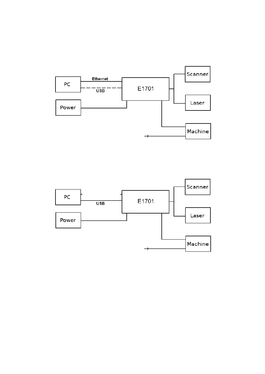
5 Position Within The System
The E1701 scanner controller system can be connected to the host via Ethernet or USB to receive laser
marking data from BeamConstruct laser marking application or from any other application which makes use of
one of the provided programming possibilties (as described below). When using Ethernet connection, it
optionally can be connected via USB too. In this case USB connection is used to retrieve BeamConstruct PRO
license from the board:
Since 100 Mbit Ethernet provides much faster data transfer than USB 2.0, this connection type is preferred.
Especially in case complex marking data with many short lines that result in many separate jump and mark
commands are used, Ethernet connection is more responsive.
When using USB connection with such data, time from sending data to the card until marking operation can be
started may be longer (up to several seconds in worst case) caused by slower USB data transfer:
In both cases the board itself is connected with the scanhead to submit 2D or 3D position information to it.
Beside of that it is connected to a laser to submit motion-synchronous laser data. Additional communication
channels between the E1701 scanner controller board and a connected machine can be done via separate IOs
of an extension board.
13
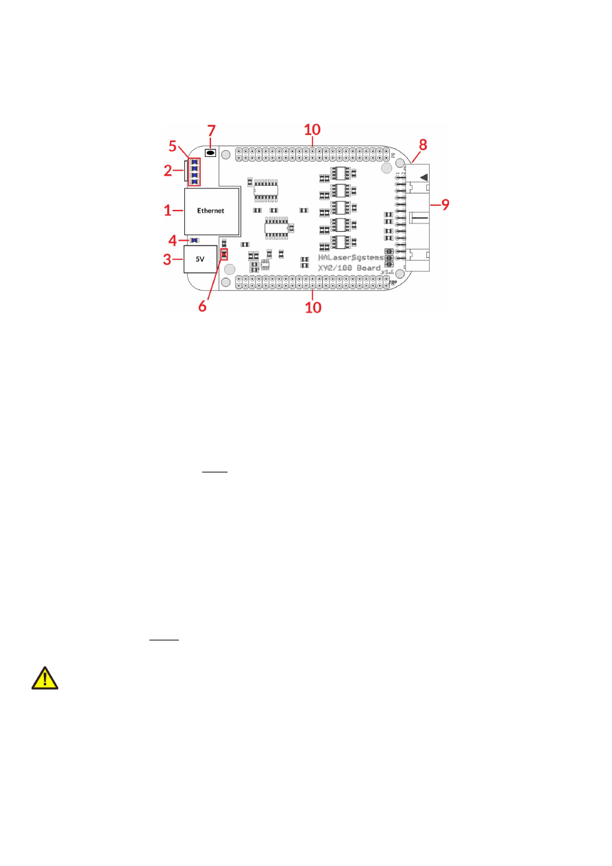
6 Boards And Connectors
6.1 E1701D XY2-100/XY3-100 Digital Laser Scanner Controller Baseboard
The E1701D Digital Laser Scanner Controller Baseboard provides following connectors and interfaces:
1. Ethernet – for communication with the host system, marking information are submitted via this path
2. USB – via miniUSB connector for providing BeamConstruct PRO license to host system and optionally
for submitting marking data from host to E1701D card (in case Ethernet is not used)
3. Power – connect with power jack 5V DC
4. Power LED – lights when power is available
5. User LEDs – show operational and error states of card
6. Laser LED – shows modulation state of laser
7. Reset-button – on-board button to restart the board completely
8. microSD-card (on bottom side) – storage place for firmware and extended configuration file, can be
used to upgrade firmware, to change the card's IP and other things more
9. Laser/Scanner signals – white 26 pin laser and scanner output connector which provides XY2-100 /
XY2-100-E scanner signals as well as laser and marking control IOs
10. Extension connectors – extension boards can be placed here in order to add some more functionality
and hardware interfaces to the board
6.1.1 Ethernet
This is a standard RJ45 Ethernet plug for connection of the board with the host system. The controller board is
accessed via this connection, all scanner and laser data are sent via Ethernet. Thus it is recommended for
security reasons to have a separate 1:1 connection from the host to the scanner controller card by using a
separate Ethernet port. In case this is not possible at least an own, physically separated sub-net for all scanner
controller cards should be set up. This network of course should be separated from normal network completely.
Ethernet connection is initialised during start-up, thus Ethernet cable connecting E1701 board and host system
needs to be plugged before the board is powered up.
By default the E1701 baseboard is using IP 192.168.2.254, thus the Ethernet network the card is connected
with needs to belong to subnet 192.168.2.0/24.
PLEASE NOTE: For security reasons it is highly recommended to not to mix a standard communication network
with an E1701 network or to connect the scanner controller card with a standard network. Here it may be
possible someone else in that network (accidentally) connects to that scanner controller and causes laser
emission.
The IP of the scanner controller can be changed. This is necessary e.g. in case an other subnet has to be used or
in case the E1701 board has to be operated in multi-head environments where more than one card will be
accessed at the same time. The IP can be configured using e1701.cfg configuration file that is placed on
microSD-card. To change the IP please perform the following steps:
1. disconnect E1701 board from power and USB
14
2. remove microSD-card
3. put microSD-card into a desktop computer, this may require a microSD- to SD-card-adapter
4. open the drive that is assigned to the card
5. open file e1701.cfg using a text editor like Notepad or kwrite
6. add a line or edit an existing line "
ip1=
", here the desired IP has to be appended (as example: when you
want to configure IP 192.168.2.13 the line has to be "
ip1=192.168.2.13
" – without any quotation
signs
7. save the file
8. eject the drive the card is assigned to
9. place the microSD-card in E1701 board (place without the use of force, notice correct orientation with
connectors of microSD-card to bottom!)
10. power up card
When User LEDs do not light up as described below, please check if microSD-card is placed in board correctly.
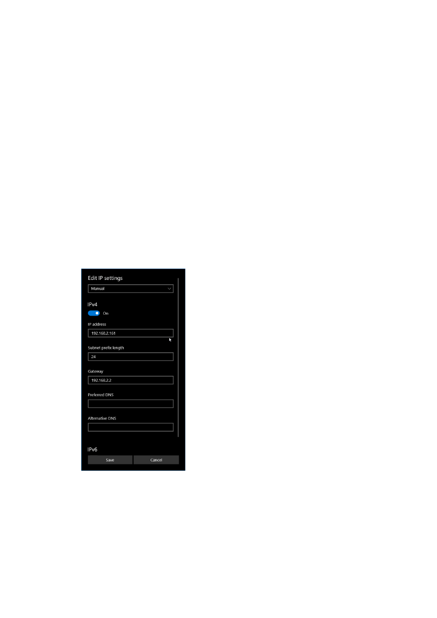
6.1.1.1 Ethernet Configuration With Windows 10
When E1701 scanner controller is accessed via Ethernet, it is recommended to have a 1:1 connection to the
host PC for security reasons. Since the controller is working with a static IP (default is 192.168.2.254) the
Ethernet port on host PC has to be configured with an IP of same subnet in order to allow access to it. For
Windows 10 (and similar) this configuration has to be done using following steps:
1. right-click the network-symbol in your taskbar
2. Select “Open network and internet settings”
3. Select “Ethernet” on the left
4. find the network interface E1701D has to be connected with and select it
5. Click the “Edit” button in section “IP settings”
6. now a window opens where “IPv4” has to be turned on and that has to be configured as follows:
There you can specify an IP for your host PC. It has to belong to network 192.168.2.xxx and can be any
number except than 192.168.2.254 (this is already the IP of the scanner card), 192.168.2.0 or
192.168.2.255.
6.1.1.2 Ethernet Configuration With Windows 11
When E1701 scanner controller is accessed via Ethernet, it is recommended to have a 1:1 connection to the
host PC for security reasons. Since the controller is working with a static IP (default is 192.168.2.254) the
15
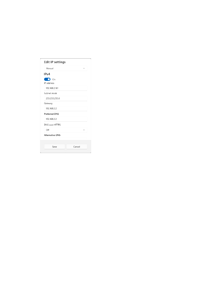
Ethernet port on host PC has to be configured with an IP of same subnet in order to allow access to it. For
Windows 10 (and similar) this configuration has to be done using following steps:
7. right-click the network-symbol in your taskbar
8. Select “Network and internet settings”
9. Select “Ethernet” in the opened list
10. find the network interface E1701D has to be connected with and select it
11. Click the “Edit” button right beside “IP assignment”
12. now a window opens where “Edit IP Settings” has to be switched from “Automatic (DHCP)” to “Manual”
13. next “IPv4” has to be turned on and the remaining parameters in this window have to be configured as
follows:
There you can specify an IP for your host PC. It has to belong to network 192.168.2.xxx and can be any
number except than 192.168.2.254 (this is already the IP of the scanner card), 192.168.2.0 or
192.168.2.255.
6.1.1.3 Ethernet Configuration With Linux
When E1701D scanner controller is accessed via Ethernet, it is recommended to have a 1:1 connection to the
host PC for security reasons. Since the controller is working with a static IP (default is 192.168.2.254) the
Ethernet port on host PC has to be configured with an IP of same subnet in order to allow access to it. For Linux
(with NetworkManager) this configuration has to be done using following steps:
1. right-click the network-symbol in taskbar
2. click "Edit Connections..."
3. select the "Wired" network interface the scanner card is connected with and press button "Edit"
16
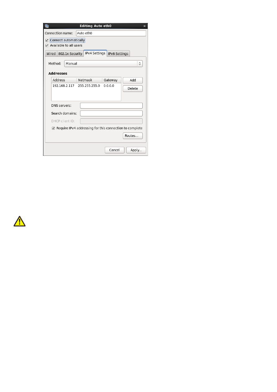
4. go to tab-pane "IPv4 Settings" and configure it as shown below:
There you can specify an IP for your host PC. It has to belong to network 192.168.2.xxx and can be any
number except than 192.168.2.254 (this is already the IP of the scanner card), 192.168.2.0 or
192.168.2.255.
6.1.2 USB
This is a standard miniUSB-connector for connection of the board with the host system. It is used to retrieve
BeamConstruct PRO license and optionally – when Ethernet is not connected – to send marking data to the
card.
PLEASE NOTE: USB 2.0 is much slower than a standard 100 Mbit Ethernet connection, so expect slower
execution in case of complex marking data!
Required device driver is installed together with installation of the HALsetup software package (Windows) or
comes with operating system by default (Linux). E1701 card appears as COM-interface on Windows using any
free number for the port. With Linux it appears as /dev/ttyACMx where "x" is any number. These numbers are
provided by the operating system automatically.
By default USB provides 5V power supply too. So whenever card has to be stopped, both USB and power have
to be disconnected in order to shut it down completely. It is not recommended to use USB as power supply, an
additional, external power should be connected in order to operate E1701 controller correctly. Nevertheless it
might be possible E1701 card can be operated on USB power only. Since this highly depends on the capabilities
of used host system, it has to be evaluated for every particular case.
When the controller is connected via USB, a BeamConstruct PRO license is provided via this interface
automatically. This is done without the need to configure anything, and as long as following conditions are true:
•
physical USB connection from controller to host PC exists
•
the COM-port (Windows) has a number smaller than COM20
•
the controller is working and the Alive-LED in blinking
It is also possible to have the USB-connection for license retrieval only and to use the Ethernet-connection to
transfer marking data to the controller, both can exist beside each other.
6.1.3 Power
Power supply for E1701 scanner controller board is done via power jack right beside Ethernet port. Power can
be supplied via a 2.1 mm x 5.5 mm centre connector when connected to a positive power supply rated at 5V DC
17
+/- 0.1V and 2.5A (smoothed, positive pole on inner contact). Do not apply voltages in excess of 5V to the DC
input. The DC power supply must be grounded.
To avoid high frequency interferences from other electrical equipment or from within the power supply, it is
recommended to place a ferrite bead at the cable close to the board. Please also check for correct shielding in
respect to the equipment the E1701 card is used within.
6.1.4 Power LED
This LED is lit as soon as the board is on some power. This means it may be functional and could emit any signals
as soon as this LED is on but it does not necessarily need to work properly since firmware may not be started at
this point. Please refer section below for LEDs that show functional state of the board.
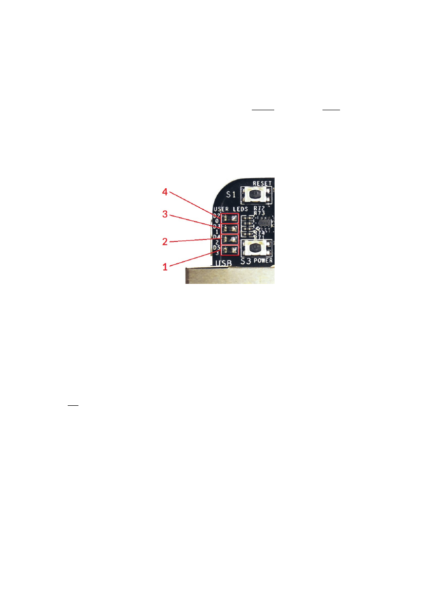
6.1.5 User LEDs
The real operational state of the card is shown by four additional LEDs described here from inner to outer
position:
1. Boot- and Alive-LED – this LED is turned on permanently as soon as the card was powered up and the
firmware boots properly. When it is not turned on after some seconds please check if the microSD-card
is placed properly and if it contains a working firmware file (for details please refer below). After boot
process has completed successfully, it starts blinking slowly. This is an alive-notification, as long as it
blinks, the board is working and ready for operation. During marking operations the blink frequency
may go down. Only in case it does not blink for more than 20 seconds, the board has died for some
reason and should be restarted.
Please note: during start-up and when the configuration parameter “eth=2” is set in e1701.cfg, the
blinking frequency can be much slower. This is the case as long as the controller tries to detect an
Ethernet connection. It ends and switches to faster blink frequency as soon as this detection is timed-
out or as soon as a connection via Ethernet or USB is established.
2. Marking Active LED – this LED is turned on as long as a marking operation is running. This LED does
not correspond to the laser gate signal, comparing to it it’s also enabled during jumps when laser is
turned off but marking operation itself is active.
3. Stop LED – this LED is lit as long as a valid external stop signal is detected.
4. Error-LED – this LED is turned on in case a fatal error occurs that normally should never happen. When
it is on, in most cases board can't continue with operation until the reason for error is removed and the
board is restarted. In case this LED is turned on please:
- check if you are using exactly one baseboard
- check if you are using E1701 extension boards only (and no other 3rd party hardware)
- check if you are using latest firmware and host software
- check all connections and cables
- undo your latest changes in hardware and configuration
If these steps do not help, please contact HALaser Systems for further assistance.
18

6.1.6 Laser LED
This LED shows modulation state of the laser and signal of laser gate output. It is turned on as long as the laser
is turned on and the laser gate is high. This LED does NOT signal the same like the marking active LED described
above since it will be turned off during jumps.
6.1.7 Reset-Button
When this button is pressed for at least 20 milliseconds, it restarts the card completely, a current marking
operation is cancelled, all signals are disabled and all remaining marking data are dropped. After releasing this
button, the board is rebooted and firmware is started again.
6.1.8 microSD-Card
The microSD card is storage place for firmware and configuration files. Here SD and SDHC cards with storage
space of up to 32 GB are supported.
To remove the microSD-card, first disconnect all power from the E1701 board completely (including USB,
Power LED has to go off). Next press microSD card gently into the board until you can hear a click-noise. Then
you can pull it out of the board. To place a microSD card, the same has to be done in reverse order: place it into
the E1701 board’s card slot and press it gently until a noise signals locking of the card. Now the board can be
powered.
E1701 baseboard is shipped with a card containing firmware and configuration files:
E1701.fwi - firmware file that is used to operate the board, to be replaced when a firmware update is
provided
E1701.cfg - configuration text file, can be edited using a text editor in order to modify cards
configuration
E1701.dat – additional data file that is used to operate the board, to be replaced when a firmware
update is provided
To use an other microSD card than the one shipped with the board, following conditions have to be met:
•
maximum total size of 32 GB (SD or SDHC card)
•
FAT32 formatted
•
using only one partition
•
BOOT-flag is set
•
E1701.fwi and e1701.dat file available on card
An additional file E1701.cfg can be placed on the card too. It contains plain ASCII text, acts as configuration file
and can contain several parameters and its values which are separated by an equal-sign. Every of the possible
parameter/value pairs has to be located in an own line. Following configuration parameters are possible within
this file:
Parameter
Description
Example
ip1
Configures IP of Ethernet port. Here only IPs in xxx.xxx.xxx.xxx
notation are allowed but no host or domain names.
ip1=192.168.2.100
specifies IP 192.168.2.100
to be used for Ethernet
interface on next startup
corrtable0
Specifies a correction table file in .ctb, .ct5, .ucf, .gcd, .xml, .crt, .txt
or .bco format to be loaded on start-up. When this parameter is
set, the specified correction table is used exclusively and all
correction data possibly sent from the host are ignored. The
correction file itself has to be located on microSD-card too.
This method has also to be used when running the controller in
stand-alone mode with .EPR files that require such a correction.
When the Error-LED is turned on after a correction table file was
configured, E1701 baseboard was not able to load it for some
reason.
corrtable0=0:/
D2_200.ctb
use file D2_200.ctb as
correction file and ignore
all correction tables
possibly sent from host
application
corrtable<i
dx>
Specifies one of up to 16 correction table file
in .ctb, .ct5, .ucf, .gcd, .xml, .crt, .txt or .bco format to be loaded on
start-up. When this parameter is set, the specified correction
corrtable7=0:/200_2
00.bco
use file 200_200.bco as
19
Parameter
Description
Example
table is used exclusively and all correction data possibly sent
from the host are ignored. The correction file itself has to be
located on microSD-card too.
This method has also to be used when running the controller in
stand-alone mode with .EPR files that require such a correction.
When the Error-LED is turned on after a correction table file was
configured, E1701 baseboard was not able to load it for some
reason.
<idx>
can be any value in range 0..15 and specifies the storage
location index of the correction file to be loaded. Later the
related correction file can be used via command
cscor
.
When
<idx>
has to be set to values greater than 0, a firmware
version 33 or newer is needed.
correction file at index
position 7 and ignore all
correction tables possibly
sent from host application
passwd
Specifies an access password that is checked when card is
controlled via Ethernet connection. This password corresponds
to password specified with function
E170X_set_password()
,
please refer below for a detailed description.
When a client computer connects to the card without sending
the correct password, Ethernet connection to this host is closed
immediately.
PLEASE NOTE: this password does not replace any network
security mechanisms and does not give the possibility to operate
E1701 controller via insecure networks or Internet! It is
transferred unencrypted and therefore can be "hacked" easily.
Intention of this password is to avoid collisions between several
E1701 cards that operate in same network and are accessed by
several software instances.
Maximum allowed length of the password is 48 characters. It is
recommended to not to use any language-specific characters.
passwd=myCardPwd
set a password
"myCardPwd"
standalone
This command can be used to disable or enable a specific stand-
alone operation mode. For a detailed description of possible
parameters, operation modes and usage please refer related
section below.
iolatch
When using one of the digital-input-controlled stand-alone
modes, this option can be used to latch the digital states in via
DIn7. For details please refer to section “6.1.11 Stand-Alone
Operation” below
iolatch=1
enable the latch-function
via DIn7
iothres
In stand-alone mode there are two conditions that cause a
loaded EPR file to be ready: it is fully loaded into the secondary,
marking buffer or a minimum amount of data is available in
secondary buffer.
Something similar is true for host-controlled operating mode:
here marking starts when
E170X_execute()
is called or when
a minimum amount of data has been transmitted to the
controller.
That minimum amount of marking data can be modified with the
parameter “iothres”. The smaller this value is, the faster marking
will start, but in this case it also may happen there are not
enough data available so that interruptions occur during
marking. So a balance between speed and a secure, non-
interrupted marking process need to be found when this value is
modified.
By default “iothres” is 80000 which should fit to most
applications, the maximum allowed value is 280000 and it should
not become smaller than 10000
iothres=120000
Set the threshold for
availability of the stand-
alone marking data to
120000
20

Parameter
Description
Example
haltedloopt
imeout
This parameter is used in stand-alone modes “haltedloop” and
“iohaltedloop” (please refer to section “6.1.11 Stand-Alone
Operation” for detailed information). It defines a timeout for the
laser in unit seconds. If the current operation is active for a
longer time, the laser is turned off. It then can be turned on only
by toggling the enable-input (ExtStart) again.
This parameter requires firmware version 35 or newer.
haltedlooptimeout=5
sets the laser timeout to 5
seconds
haltedloop
buffer
This parameter is used in stand-alone modes “haltedloop” and
“iohaltedloop” (please refer to section “6.1.11 Stand-Alone
Operation” for detailed information). It defines a maximum
buffer size for the marking data. The buffer size should have a
size of 17000000 at max. The minimum size depends on the
specific application, in fact, when it is set to some too small
values, drop-outs in marking operation may occur.
Data which are already buffered in this marking mode can't be
modified any longer. So any change on marking speed, power or
similar (done e.g. by commands “
cjsor
”, “
cmsor
” or “
cpwor
”)
will apply only to data which are not yet buffered. And as bigger
as this buffer is, as longer it takes until the first new data after
change of any of these parameters can be emitted.
This parameter requires firmware version 33 or newer.
haltedloopbuffer=10
0000
set the buffer to a
maximum size of 100000
commands which is similar
to data for about 1 second
marking time
autofile
Loads a special .EPR stand-alone file from SD-card in some
specific stand-alone modes. For a detailed description of possible
parameters, operation modes and usage please refer related
section below.
autofile=0:/
markdata.epr
loads a file markdata.epr
from disk; here 0:/ specifies
the SD-card to be used.
The .EPR-file itself can be
generated within
BeamConstruct out of a
normal .BEAMP project
file.
iobuff
Pre-loads one or more .EPR files to the RAM of the controller to
allow faster switching in “ioselect” or “idxselect” stand-alone
mode. This command can not be used to load file “0.EPR”
iobuff=1
iobuff=3
pre-load files 1.EPR and
3.EPR on board start-up
mipout
Configure a Digi I/O output pin to be used as “mark in progress”-
signal by default; here an output bit number in range 0..7 has to
be configured which will be set to HIGH as long as a marking
operation is in progress, the value given here can be overwritten
by API-function
E170X_digi_set_mip_output()
;
this parameter requires firmware version 30 or newer
mipout=1
use DOut1 for mark-in-
progress signal
wetout
Configure a Digi I/O output pin to be used as “wait for external
trigger”-signal by default; here an output bit number in range 0..7
has to be configured which will be set to HIGH as long as a
marking operation is in progress and the controller is waiting for
an external trigger signal to arrive at ExtStart input, the value
given here can be overwritten by API-function
E170X_digi_set_wet_output()
;
this parameter requires firmware version 30 or newer
wetout=0
use DOut0 for mark-in-
progress signal
digiinit
Initialises the digital outputs on firmware start-up with the given
defaults. This overrides the hardware defaults. The default
digital values set here are NOT available on power up but a few
seconds later after firmware has been loaded and started.
This function requires firmware version 32 or newer.
digiinit=2
set DOut1 to HIGH initially
and all other outputs to
LOW
21

Parameter
Description
Example
digimask
Masks the digital inputs and specifies which inputs can be read.
All input bits which are ignored by this command by setting the
related value to 0, are no longer read. This may be useful for
applications where encoder inputs are used together with a
IOSelect stand-alone operation and where the random state of
the encoder has to be masked out.
This function requires firmware version 32 or newer.
digimask=253
use only DIn2..DIn7 as
input and ignore DIn0 and
DIn1
digidebc
Sets a debouncing time / filter time for the digital inputs of the
Digi IO extension board in order to not to let the inputs react on
noise or bouncing of mechanical inputs. The debouncing value is
given in time-units where every time-unit is equal to 31 usec. By
default 7 time-units are set.
digidebc=10
set the debounce-time to
310 usec
lasergate
By default, the laser on/off information is provided via the
LaserGate output and with CMOS logic voltage level. With this
parameter, a digital output of the Digi I/O extension board can be
specified, to provide the laser gate signal in parallel.
Please refer to “6.4 E1701 Digi I/O Extension Board” for further
details about the digital interface.
This configuration parameter requires firmware version 41 or
newer
lasergate=3
Use DOut3 to provide the
laser gate signal
tunereadyo
ut
In stand-alone modes, the ready-state of a loaded stand-alone
project is signalled via DOut0 by default (please refer to section
“6.1.11.3 Stand-Alone Control” for further details). Using this
parameter, the used output can be changed. Here following
values can be given:
•
0 – DOut0 (default)
•
1 – LaserA (has to be configured as GPO via the related
tune-flag)
•
2 – LaserB (has to be configured as GPO via the related
tune-flag)
This parameter requires firmware version 13 or newer.
tunereadyout=1
use LaserA to signal state
“ready” in stand-alone
mode
tunemarko
ut
In stand-alone modes, the ready-state of a loaded stand-alone
project is signalled via DOut1 by default (please refer to section
“6.1.11.3 Stand-Alone Control” for further details). Using this
parameter, the used output can be changed. Here following
values can be given:
•
0 – DOut1 (default)
•
1 – LaserA (has to be configured as GPO via the related
tune-flag)
•
2 – LaserB (has to be configured as GPO via the related
tune-flag)
This parameter requires firmware version 13 or newer.
tunemarkout=2
use LaserB to signal state
“ready” in stand-alone
mode
tune
Enables special functions and features that are not activated by
default. As parameter a number can be handed over that
specifies the functions to be enabled. Starting with firmware
version 41 the number can also be specified as hexadecimal
value when it is prefixed with “0x”. Following numbers can be
concatenated by adding them:
1 (0x01) – use DIn7 of Digi I/O Extension Board as external
trigger, this disables ExtStart input of E1701 Baseboard and LP8
Extension Board
2 (0x02) – use additional marking encoder inputs on DIn2 and
DIn3 for 2D on-the-fly operations (requires firmware version 25
or newer)
4 (0x04) – enable storage of serial number count values to
microSD card; this option is useful in case of stand-alone
operation mode when dynamic data with serial number counting
tune=1
disables ExtStart input and
switches over external
trigger function to DIn7
input
tune=0x1000
force the acanner output
to use XY2-100E mode
22
Parameter
Description
Example
is used. When it is set, the current count value of all used serial
numbers is stored and reloaded on next power up. Thus their
values are not get lost when power was turned off. The values
are stored in a file with the same name like the "autofile" or the
currently loaded .epr file but with extension ".ser".
ATTENTION: The file is saved on the FatFS formatted microSD
card. FatFS is NOT fault-proof, means it can be corrupted when
power is turned off during writing. So when this option is
enabled, user has to ensure power is NOT turned of while the
card writes to disk. Writing of serial number states is always
done in case they have changed, then it is started when state
LED of E1701D board is switched off. Write operation is finished
when this LED is turned back on the next time. So to ensure data
are written successfully, it is recommended to let this LED blink
two times after last mark operation has been finished. In
automated environment this can be ensured by following
procedure:
1. stop all marking operations
2. ensure no new marking operation is triggered
3. wait for 2 seconds
4. turn power off
ATTENTION: due to this limitation it is not recommended to
work with this option but to save the state of the serial numbers
by sending ASCII command "
cssta
" instead (please refer below
for details)!
This value requires firmware version 12 or later.
8 (0x08) – invert LaserGate output to work as active HIGH
signal; when this option is set, logic of LaserGate-LED changes
too, it is on as long as laser is turned off and it is off as long as
laser is on (requires firmware version 16 or newer)
16 (0x10) – invert LaserA output to work as active HIGH signal
(requires firmware version 16 or newer)
32 (0x20) – invert LaserB output to work as active HIGH signal
(requires firmware version 16 or newer)
64 (0x40) – use LaserA output as GPO (general purpose output
pin); when this flag is set, LaserA output is no longer able to emit
a frequency but can be used as digital output pin; when this value
is set, a tune-value of 16 (invert LaserA) is ignored. This flag has
to be set e.g. when LaserA has to be used together with
tunereadyout
or
tunemarkout
parameter.
128 (0x80) – use LaserB output as GPO (general purpose output
pin); when this flag is set, LaserB output is no longer able to emit
a FPK pulse but can be used as digital output pin; when this value
is set, a tune-value of 32 (invert LaserB) is ignored. This flag has
to be set e.g. when LaserA has to be used together with
tunereadyout
or
tunemarkout
parameter.
4096 (0x1000) – operate in enhanced XY2-100 18 bit mode;
when this value is added to the tune-parameter, the controller
outputs more accurate 18 bit position data instead of the
standard 16 bit values in normal operation mode (requires
firmware version 24 or newer)
8192 (0x2000) – operate in XY3-100 mode; when this value is
23
Parameter
Description
Example
added to the tune-parameter, the controller outputs more
accurate position data instead of the standard 16 or 18 bit values
in normal operation mode (requires firmware version 39 or
newer)
32768 (0x8000) – invert the mark-in-progress signal (requires
firmware version 32 or newer)
65536 (0x10000) – invert the wait-external-trigger signal
(requires firmware version 32 or newer)
524288 (0x80000) – inverts the logic of the ExtStop input; by
default, the stop-input is LOW and has to be set to HIGH in order
to stop a running operation. When this flag is set, this is inverted,
ExtStop has to kept HIGH for normal operation and a stop is
performed as soon as it goes to LOW.
This flag requires firmware version 41 or newer.
2097152 (0x2000000) – halt the current marking operation
when ExtStart input is at LOW; with this tune-flag set, the
ExtStart input not only reacts on the rising edge to mark when
waiting for an external trigger, it also requires to be HIGH in
order to continue marking. So ExtStart acts as some kind of
“enable” input.
This flag requires firmware version 41 or newer.
4194304 (0x400000) – invert the LP8 signal of LP8 Extension
(requires firmware version 41 or newer)
8388608 (0x800000) – invert the MO (main oscillator) signal of
LP8 Extension (requires firmware version 41 or newer)
16777216 (0x1000000) – inverts the logic of the ExtStart input.
By default, the start-input reacts on a rising edge. When this flag
is set, this is inverted and a falling edge is expected to release an
external trigger. This also has an effect on the behaviour of tune-
flag 0x2000000, it is inverted too.
This flag requires firmware version 41 or newer.
sntp1
Allows to specify the IP of an SNTP time server. This option can
be used in case of Ethernet usage to synchronise controller with
an external time source. E1701D tries to connect to this server
after initialisation of Ethernet interface and – if not successful –
a few more times. These additional connection attempts are
done whenever the state-LED is switched on.
ATTENTION: when this function has to be used, the network or
host-computer the controller is connected with needs to be able
to route this request. This is a potentially dangerous operation
because a connection between encapsulated machine network
and open and dangerous Internet has to be established. Since
this is NOT RECOMMENDED in general, this option should be
used ONLY when it is 100% sure there is no possibility for people
from outside to intrude the machine network! Instead of that it is
recommended to set system time manually using host-computer
and ASCII command "cstime" (please refer below). Alternatively
it is also possible to contact an own, network-internal NTP-
server.
When this option is used, the gateway and netmask have to be
configured for the controllers Ethernet interface
This parameter requires firmware version 12 or later.
sntp1=83.170.1.42
–
IP of time server at
3.de.pool.ntp.org is used
for SNTP time retrieval
(not recommended since
this requires a connection
to potentially dangerous
Internet!)
24

Parameter
Description
Example
sntp1offset This value corresponds to sntp1 parameter above, it is used
when system time is retrieved from an external time server to
set an offset to the time returned from this server. The offset has
to be specified in unit seconds.
This parameter requires firmware version 12 or later.
sntp1offset=-3600
–
specifies an offset of minus
one hour to the time
returned from timeserver.
So when the time server
would return a current
time of 11:42:17, the
system time of the
controller would be set to
10:42:17 with this value
gw1
Specifies a gateway-address for the scanner controllers Ethernet
interface. This option belongs to parameter "ip1" and has to be
set in case "sntp1" is used.
This parameter requires firmware version 12 or later.
gw1=192.168.2.1
– use
192.168.2.1 as gateway
nm1
Specifies the netmask for the scanner controllers Ethernet
interface. This option belongs to parameter "ip1" and has to be
set in case "sntp1" is used.
This parameter requires firmware version 12 or later.
nm1=255.255.255.0
–
use upper 24 bits of
current IP for netmask
node0
Specifies the IP of an external HALnode Compact Ethernet IO
module to be used for additional 8 digital in- and outputs (lower
8 bits of an additional 16-bit IO port). Once configured, the
HALnode’s digital ports are used as they were a part of the
controller. This functionality requires firmware version 46 or
newer.
node0=192.168.1.253
– use the digital IOs of the
HALnode at the IP
192.168.2.253
node1
Specifies the IP of an external HALnode Compact Ethernet IO
module to be used for additional 8 digital in- and outputs (upper
8 bits of an additional 16-bit IO port). Once configured, the
HALnode’s digital ports are used as they were a part of the
controller. This functionality requires firmware version 46 or
newer.
node1=192.168.1.252
– use the digital IOs of the
HALnode at the IP
192.168.2.252
eth
This parameter specifies the behaviour of the Ethernet interface.
Here following values can be set:
•
0 – Ethernet network interface is disabled completely.
This means it is no longer possible to connect to E1701
via Telnet or via BeamConstruct. All SNTP-
functionalities are disabled too. This option can be used
to suppress illegal access to Ethernet, to save several
seconds of startup-time and to save some power.
•
1 – this mode enables the Ethernet interface and checks
once at the beginning if some Ethernet hardware is
connected to the controller card; when the “eth”-
parameter is not specified at all, the resulting behaviour
is the same
•
2 – this enables Ethernet polling mode; instead of
checking for an Ethernet device only once during boot,
in this mode the interface is polled regularly until an
electrical connection is detected. As long as the
controller is polling, the Alive-LED blinks very slow and
toggles once in about 20 seconds, when an Ethernet
device was detected, the blink frequency changes to
normal speed;
PLEASE NOTE: when this mode is used, access via USB is
limited, so “eth” should be set to “2” only when no
communication via USB is intended.
The “eth”-value of 2 requires a firmware version 39 or
newer
eth=0
– turn off Ethernet
interface completely
pethd
When Ethernet connection is used, it has to be established on
power-up of the controller card as this connection is set-up and
pethd=20
- halt
initialisation of the
25

Parameter
Description
Example
configured by the controller only once during boot. There may be
situations where the other side of the Ethernet connection can
not boot up as fast as E1701. In such cases this parameter can be
used. It delays initialisation of Ethernet by the time given as
parameter. The time is specified in unit “delayticks” where one
“delaytick” is equal to about 0,5 seconds.
As long as the controller is halted during initialisation due to this
parameter, this is signalled by the Stop-LED (please refer to 6.1.5
User LEDs for details).
This feature requires a firmware version 34 or newer.
controller for about 10
seconds prior to
initialisation of Ethernet
interface
cswaf
Sets a factor in unit bits per mm that is used with all commands
that specify some distance or position (such as cspof). When this
factor is set to a proper value, the given positions/distances can
be specified in unit um instead of bits.
This parameter requires a firmware version 45 or newer.
cswaf=671089
– set the
conversion factor from bits
to mm for a 100x100 mm
working area
6.1.8.1 Firmware Update
As described above the firmware is located on microSD-Card and therefore can be updated easily:
1. remove the microSD-Card as described above
2. download a new firmware from
https://halaser.systems/download/Firmware/E1701
(the higher the
number in the file name, the newer the firmware is)
3. copy the contents of this ZIP-file to microSD-Card (please take care about e1701.cfg in case it contains
a changed configuration)
4. reinsert microSD-Card as described in previous section
6.1.9 Laser/Scanner Signals
The white 26 pin connector provides several signals to be used to control up to three galvos of a scanhead and a
laser source. It can be connected to an XY2-100 or XY2-100-E compatible scanner system via an adapter cable
which splits XY2-100 and laser/input control signals. The connector is a white one to avoid confusion when a
LP8 Extension Board is used too. The connector provides following signals:
Upper
Row Of
Pins
Signal
Voltage
Remarks
Lower
Row Of
Pins
Signal
Voltage
Remarks
1
CLK-
XY2-100- /
XY2-100-E-
compatible
signals
2
CLK+
XY2-100- /
XY2-100-E-
compatible
signals
3
SYNC-
4
SYNC+
5
X-
6
X+
7
Y-
8
Y+
9
Z-
10
Z+
11
LaserA
CMOS, 0/5V,
max 14 mA
Laser control
signals
12
GND
GND
13
Laser
Gate
CMOS, 0/5V,
max 14 mA
14
GND
GND
15
LaserB
CMOS, 0/5V,
max 14 mA
16
ExtStart
CMOS, 0/5V
Input control
signals
17
5V
5V
18
ExtStop
CMOS, 0/5V
19
do not
connect
20
GND
GND
21
GND
GND
22
GND
GND
23
do not
connect
24
do not
connect
25
do not
connect
26
do not
connect
Laser Gate provides laser modulation signal, turns on the laser during marks and off during jumps.
26

LaserA usage depends on software configuration and control, it is able to output a pulse-width modulated
frequency (e.g. for controlling CO
2
lasers), CW/continuously running frequency (e.g. for fiber lasers) or Q-
Switch signal (e.g. for YAG lasers) in range 25 Hz..20 MHz.
LaserB can be used for emitting a FPK pulse (e.g. for YAG lasers).
ExtStart expects a CMOS-level input signal in respect to GND and can be used as external trigger signal to start
operations when a HIGH-signal is detected at input pin.
ExtStop expects a CMOS-level input signal in respect to GND and can be used as external stop-signal in order
to stop a running marking operation by using a HIGH-signal at input pin.
The E1701D can operate in XY3-100 mode too. This requires a firmware version 37 or newer. The controller
can be connected to an XY3-100 compatible scanner system via an adapter cable which splits XY3-100 and
laser/input control signals. The scanner connector is a white one to avoid confusion when a LP8 Extension
Board is used too. The connector provides following signals:
Upper
Row Of
Pins
Signal
Voltage
Remarks
Lower
Row Of
Pins
Signal
Voltage
Remarks
1
A-
XY3-100-
compatible
signals
2
A+
XY3-100-
compatible
signals
3
B-
4
B+
5
C-
6
C+
7
D-
8
D+
9
10
11
LaserA
CMOS, 0/5V,
max 14 mA
Laser control
signals
12
GND
GND
13
Laser
Gate
CMOS, 0/5V,
max 14 mA
14
GND
GND
15
LaserB
CMOS, 0/5V,
max 14 mA
16
ExtStart
CMOS, 0/5V
Input control
signals
17
5V
5V
18
ExtStop
CMOS, 0/5V
19
do not
connect
20
GND
GND
21
GND
GND
22
GND
GND
23
do not
connect
24
do not
connect
25
F-
XY3-100
backchannel
1)
26
F+
XY3-100
backchannel
1)
1)
Requires hardware revision 1.5 or newer
Laser Gate provides laser modulation signal, turns on the laser during marks and off during jumps.
LaserA usage depends on software configuration and control, it is able to output a pulse-width modulated
frequency (e.g. for controlling CO
2
lasers), CW/continuously running frequency (e.g. for fiber lasers) or Q-
Switch signal (e.g. for YAG lasers) in range 25 Hz..20 MHz.
LaserB can be used for emitting a FPK pulse (e.g. for YAG lasers).
ExtStart expects a CMOS-level input signal in respect to GND and can be used as external trigger signal to start
operations when a HIGH-signal is detected at input pin.
ExtStop expects a CMOS-level input signal in respect to GND and can be used as external stop-signal in order
to stop a running marking operation by using a HIGH-signal at input pin.
6.1.9.1 XY2-100 Connection Cable
E1701D scanner controller board can operate an XY2-100-compatible scanner system directly. Here an
adapter-cable is required that splits XY2-100 signals and additional laser/input control signals. Using such a
27
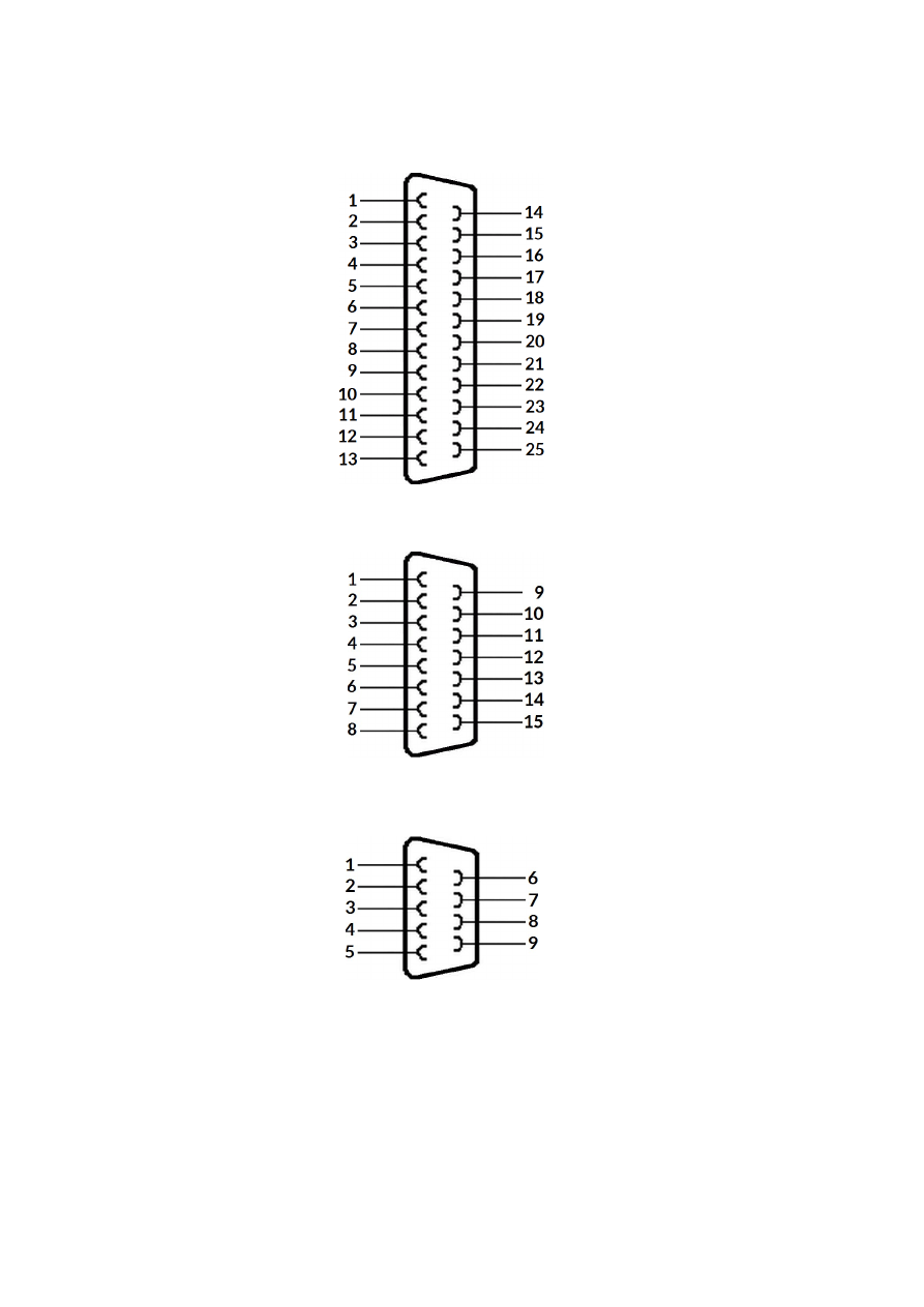
cable white 26 pin connector described above should be converted to a female, XY2-100-compatible, 25 pin
SUB-D connector (to connect with scanhead) and a female 9 pin SUB-D connector (which provides laser signals
and start/stop inputs).
Pinout of a D-SUB25 XY2-100 connector should be conform to standard with ground-signals (GND) at pins 11,
23 and 24:
1 – CLK-
2 – SYNC-
3 – X-
4 – Y-
5 – Z-
11 – GND
14 – CLK+
15 – SYNC+
16 – X+
17 – Y+
18 – Z+
23 – GND
24 – GND
XY2-100 status signals from scanhead are not used for E1701D.
Pinout of a limited D-SUB15 XY2-100 connector depends on used scanhead but typically looks like this:
1 – CLK-
2 – SYNC-
3 – X-
4 – Y-
5 – Z-
8 - GND
9 – CLK+
10 – SYNC+
11 – X+
12 – Y+
13 – Z+
15 – GND
XY2-100 status signals from scanhead are not used for E1701D.
Possible pinout of 9 pin SUB-D laser signal and control connector is shown below:
1 – LaserA
2 – Laser Gate
3 – LaserB
4 – 5V
5 – GND
6 – GND
7 – GND
8 – ExtStart
9 – ExtStop
Please note: to avoid this complex and potentially error-prone wiring, you also can use the E1701dock for
simple and easy 1:1 connection using a standard cable. For details please refer to section “6.6 E1701dock
Extension Board”.
6.1.9.2 XY3-100 Connection Cable
E1701D scanner controller board can operate an XY3-100-compatible scanner system directly. Here an
adapter-cable is required that splits XY3-100 signals and additional laser/input control signals. Using such a
cable white 26 pin connector described above should be converted to a female, XY3-100-compatible, 25 pin
28
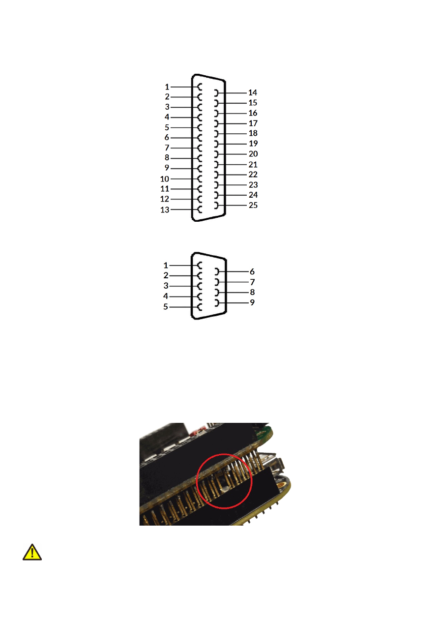
SUB-D connector (to connect with scanhead) and a female 9 pin SUB-D connector (which provides laser signals
and start/stop inputs).
Pinout of a D-SUB25 XY3-100 connector should be conform to standard with ground-signals (GND) at pins 11,
23 and 24:
1 – A-
2 – B-
3 – C-
4 – D-
6 – F-
11 – GND
14 – A+
15 – B+
16 – C+
17 – D+
19 – F+
23 – GND
24 – GND
XY3-100 E+- signals are not used for E1701D.
Possible pinout of 9 pin SUB-D laser signal and control connector is shown below:
1 – LaserA
2 – Laser Gate
3 – LaserB
4 – 5V
5 – GND
6 – GND
7 – GND
8 – ExtStart
9 – ExtStop
Please note: to avoid this complex and potentially error-prone wiring, you also can use the E1701dock for
simple and easy 1:1 connection using a standard cable. For details please refer to section “6.6 E1701dock
Extension Board”.
6.1.10 Extension Connectors
The two extension connectors on each side of the board can be used to place extension boards with additional
peripheral interfaces. The extension connectors are designed to place/remove boards from time to time but
they are not intended for constant hardware changes. So changing extension boards repeatedly and often e.g.
as permanent part of a production process is not recommended.
Key pin closed on lower connector and missing in upper board to ensure correct orientation
PLEASE NOTE: when placing a new extension board
1.check correct orientation and position of the key pin which is closed in connector
29
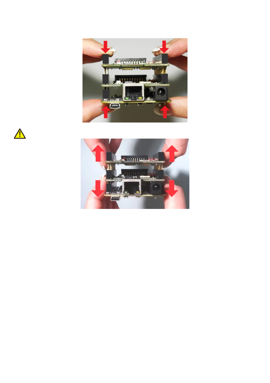
2.place the pins of the extension boards onto the extension connectors exactly
3.move down the extension board by pressing on its extension connectors gently; DO NOT PRESS THE BOARD
ITSELF BUT ONLY THE CONNECTORS!
PLEASE NOTE: When removing an extension board DO NOT pull on the extension connectors but hold both
boards on their long side directly at the PCBs edges:
Due to of the large number of pins, it is easy to plug in an extension but more difficult to pull it out. So when
removing an extension board, it is recommended to be very slow and to carefully pull each side up just a little bit
to avoid bending of the pins as they exit.
6.1.11 Stand-Alone Operation
E1701 scanner controller cards can be operated in stand-alone mode. In this mode all marking data are stored
on SD-card and the board can operate without direct control of a host-PC that sends the data to be marked.
Such stand-alone marking data can be created e.g. in BeamConstruct marking software.
The names of these stand-alone files have to be in format 8.3, means the filename has to consist of eight
characters at max, followed by a file extension which consists of 3 characters. The base-stand-alone file comes
with a file-extension .EPR. In case the stand-alone file contains dynamic data, a second file with the same
filename but the extension .DAT is created (for details about dynamic stand-alone data please refer to section
“6.1.11.1 Create Stand-Alone Data with BeamConstruct”). When a stand-alone-mode of type “ioselect” is used,
the filename has to follow some specific rules too, here it typically has to be a number which corresponds to the
selection done at the digital inputs (for details about the different stand-alone modes and their behaviour
please refer to section “6.1.11.2 Stand-Alone Configuration Parameters”).
6.1.11.1 Create Stand-Alone Data with BeamConstruct
To use BeamConstruct for generation of stand-alone data for E1701 scanner controllers, the card has to be
fully configured (including all scanner, laser and pen-parameters). Next the marking data to be stored on SD-
30

card have to be created. To generate stand-alone data, menu "Processing", sub-menu "Write Marking Data to
File" or "Send Named Marking Data" has to be selected.
First one gives the possibility to write the data to microSD card when E1701 is switched off and the microSD
card is plugged into host PC. Here it is recommended to use file extension ".EPR" for the file generated by
BeamConstruct. Next it is also recommended to always let BeamConstruct write to microSD card directly
because sometimes more than only one file is created. Direct write operation to BeamConstruct ensures all
files are available on microSD and no data can be forgotten to be copied.
The second variant allows to download the stand-alone data to the controller while it is connected and running.
Precondition for sending data to a running controller are:
•
no mark operation is in progress (controller is idle)
•
no stand-alone project is loaded (please refer to description of ioselect-mode and stand-alone control
commands below).
•
a valid name is given in style 0:/filename.epr
This operation creates the .EPR-file and all additional files on microSD card of the running controller
automatically.
PLEASE NOTE: such an .EPR-stand-alone file can NOT be converted back to vector data that could be edited in
BeamConstruct! Creating these files is a one-way-conversion of your projects. Thus it is recommended to save
these projects twice – once as normal .BEAMP-File which can be loaded and modified later and once as .EPR-
file which has to be used on SD-card. This also means such .EPR-files are protected so that it is possible to give
away designs to some end-users which shall not be able to modify them.
E1701 controller supports all static data in stand-alone mode (like all kinds of static geometries, output signals,
waiting for input commands, waiting for trigger, all laser- and scanner parameters). But it does not store the
vector data using a possibly configured correction table! To get a valid correction for stand-alone operations,
the related correction file has to be saved on microSD card and needs to be activated using parameter
"corrtable0" in e1701.cfg configuration file (please refer to description above).
Next E1701 scanner card supports dynamic content when following conditions are met:
•
a text element uses one of the laser vector font families "Roman", "Script" or "Times" and it makes use
of an input element or
•
a text element makes use of a TrueType font and it makes use of an input element; here any available
TrueType font can be used and several hatch-patterns can be applied
for both types of text some limitations apply (only left t
→
o right orientation, no
scaling/rotation/slant/mirroring is applied to the font and only the characters
' ', !, ", #, $,
%, &, \, (, ), *, +, ,, -, ., /, 0, 1, 2, 3, 4, 5, 6, 7, 8, 9, :, ;, <, =,
>, ?, @, A, B, C, D, E, F, G, H, I, J, K, L, M, N, O, P, Q, R, S, T, U, V,
W, X, Y, Z, [, \, ], ^, _, `, a, b, c, d, e, f, g, h, i, j, k, l, m, n, o,
p, q, r, s, t, u, v, w, x, y, z, {, |, }
and
~
can be used, firmware version 29 or
newer is required, BeamConstruct version 4.8 or newer is required); or
•
a barcode element uses type "DataMatrix" with option "MergeCells" disabled and it makes use of an
input element
•
any kind of hatch and combined hatches can be applied to a barcode element (but not to a text element)
•
marking output is neither XY-flipped nor mirrored nor rotated or slanted
•
when an input element of type “Serial Number” is used, serial number counting is done according to the
settings of the related element
•
when an input element of type “CSV File Data” is used, elements out of a CSV-table can be read and
used for the dynamic element:
the CSV-file itself needs to be placed on the SD-card and has to use the same name like the EPR file but
with extension CSV (so when the stand-alone file is named “data.epr”, the CSV-file needs to be named
“data.csv”), resulting from that one EPR file can handle exactly one CSV file;
supported parameters of the CSV input element are the column separator, the data column to read the
data from and the “Endless loop” option (for details please refer to the manual of BeamConstruct);
this feature requires a firmware version 40 or newer
•
when any input element is used, the contents of the text/barcode can be changed via command
“
cstxt
”, in this case the automatic updating of the input element has no effect
31

When these conditions are met, a text or barcode can be modified during stand-alone operation either via
stand-alone control commands as described below or via a Serial Number input element that is applied to it in
BeamConstruct. Here all serial number, time, date and formatting functions of this input element are
supported. To get a valid time in stand-alone mode, it needs to be set after boot-up via stand-alone control
commands (as described below) or a SNTP time server has to be configured to retrieve current time from an
external source (please refer to description e1701.cfg parameters above).
6.1.11.2 Stand-Alone Configuration Parameters
Within e1701.cfg configuration file of E1701 scanner controller one of the following stand-alone operation
modes can be selected via the configuration parameter "standalone":
standalone=off
Stand-alone mode is fully disabled, the card acts as normal, host-PC-controlled device and all .epr-files on the
SD-card are ignored. Digital outputs are not toggled since no stand-alone operational states have to be
signalised here (please refer next section).
standalone=auto
Stand-alone mode is enabled, a file specified by and additional parameter "autofile" is loaded and prepared for
marking. Marking of this file is started only when an external trigger signal is detected. The file itself has to be
specified via additional configuration parameter that gives the filename of the stand-alone file to be loaded. As
an example a parameter: "
autofile=0:/myfile.epr
" would try to load the file "myfile.epr" from SD-card
and prepare it for marking. In this mode the digital outputs are toggled as described in next section.
standalone=loop
This is the same like mode "auto" described above, but using "loop" the E1701 controller does NOT wait for an
external trigger signal! So when no trigger points are set in stand-alone datafile itself, in this mode marking
would be done in an infinite loop, repeating the given "
autofile
" again and again.
standalone=haltedloop
This is the same like mode "loop" described above, but marking does not start immediately. By default the
controller is in state “halt” until the ExtStart input is set to HIGH level. Marking continues only as long this input
stays at HIGH. When it goes back to LOW, marking is continued until the laser is turned off the next time
(defined by the geometry which is currently loaded) and it is halted again. Next time ExtStart goes to HIGH,
marking continues at the position where it was halted before.
Please note: for this mode it is recommended to have marking data with vectors that are interrupted by jumps
from time to time. When ExtStart gows to LOW, marking continues until the next jump is found. This means,
when the controller processes a complex, long-lasting vector, marking will continue for the whole time this
vector needs although ExtStart is already wt LOW. So the laser is never interrupted and turned off within a
mark operation.
This mode requires firmware version 27 or newer.
In this mode the timeout-parameter “
haltedlooptimeout
” is used.
standalone=iohaltedloop
This mode is a combination out of "haltedloop" described above and “ioselect” described below (please refer
there for usage details). In this mode a project can be selected via digital inputs but it is started immediately and
marked in an endless loop as long as ExtStart input is HIGH (so the level at ExtStart is checked, not the rising
edge of an applied signal). When a different project is selected by applying a different input pattern at DIn
digital inputs, the current project is cancelled and the new one is started in a loop again.
This mode requires firmware version 28 or newer.
In this mode the timeout-parameter “
haltedlooptimeout
” is used.
standalone=ioselect
32
This mode requires Digi I/O Extension Board (please refer below). Here it is possible to select one of 256 stand-
alone marking jobs via the digital inputs. The number that results out of the input pattern of the Digi I/O input
lines specifies the filename of the marking job that has to be loaded from SD card:
Selected input(s)
Stand-alone file loaded from SD-card
All inputs set to LOW (not recommended to be used)
0.epr
DIn0 set to HIGH
1.epr
DIn1 set to HIGH
2.epr
DIn0 and DIn1 set to HIGH
3.epr
DIn2 set to HIGH
4.epr
DIn0 and DIn2 set to HIGH
5.epr
DIn1 and DIn2 set to HIGH
6.epr
DIn0, DIn1 and DIn2 set to HIGH
7.epr
DIn3 set to HIGH
8.epr
…
…
DIn4 set to HIGH
16.epr
…
…
DIn5 set to HIGH
32.epr
…
…
DIn6 set to HIGH
64.epr
…
…
DIn7 set to HIGH
128.epr
…
…
All inputs set to high
255.epr
PLEASE NOTE: 0.epr (no inputs set to HIGH) can be used but it is not recommended to do that. This value
should be reserved for "no job active" to set the card into an inactive mode also in stand-alone operational
mode. This may be necessary e.g. when new project data are downloaded to the controller without removing
the SD-card.
Marking of a IO-selected job is started by external trigger signal (ExtStart input). When the input pattern at
DIn0..DIn7 changes during marking, the currently running operation is continued and the other stand-alone job
is loaded after marking operation has finished. In this mode the digital outputs are toggled as described in next
section.
In stand-alone mode “ioselect” and “idxselect” .EPR-files are loaded from microSD card as soon as a new input
pattern is detected at digital inputs or as soon as a new index is loaded by command “clepr”. Depending on the
size of the .EPR file and the speed of the microSD card, this may take a time that is too long for high-speed
applications. Thus it is possible to operate such projects from controller's RAM completely: in e1701.cfg the
numbers of the files to be loaded have to be specified with parameter “iobuff”, it can be used up to 20 times and
expects the number of the file (so a line “iobuff=3” would be responsible for preloading file “0:/3.epr”), file
“0.epr” can not be loaded by this command.
Now these files are loaded into RAM and switching from one to an other is done much faster since toggling
between them is done controller-internal and no more disk-operations are necessary for that.
PLEASE NOTE: when too much too large .EPR files are selected for preloading, this may exceed the available
memory on card. This is signalled by the Error LED turned on and an appropriate message is stored in log buffer.
In such a case a proper operation is no longer guaranteed.
The prebuffer-feature requires firmware version 27 or newer.
standalone=idxselect
33

This mode works exactly like the mode “ioselect” (described above), but it does not need the Digi I/O Extension
board. Instead of that, loading of a file can be done via an index number and the command
clepr
. There the
number of the file to be loaded has to be given. For a full description of all functions and features of mode
“idxselect”, please refer the “ioselect” description above.
This stand-alone mode requires a firmware version 35 or newer.
iolatch=1
This option can be enabled for one of the digital-input-controlled stand-alone modes “ioselect”, “idxselect” and
“iohaltedloop”. When this option is set to 0 or when it does not exist in e1701.cfg, the digital input bitpattern at
DIn0..DIn7 is used as new input value as soon as it is detected. When it is enabled, DIn7 is used as latch-bit.
Then the digital input bitpattern at DIn0..DIn6 is used only when DIn7 is set to HIGH. So a proper method of
selecting a digital input bitpattern with latch enabled would be:
•
ensure DIn7 is at LOW
•
apply the desired bitpattern at DIn0..DIn6
•
wait for the maximum time the input bits may need to settle (depends on the external hardware and its
capabilities)
•
set DIn7 to HIGH
•
wait until DOut0 goes to LOW
•
wait until DOut0 goes back to HIGH (when a valid bitpattern was applied that corresponds to an
existing EPR file) or until loading timeout has elapsed (when a bitpattern has been applied where no
EPR file exists for
•
set DIn7 to LOW
So as long as DIn7 is at low, state-changes at DIn0..DIn6 are ignored and the last detected bitpattern is used. In
this mode only 127 different input bitpatterns are possible as DIn7 is used as latch bit.
This function is available in firmware versions 38 or newer.
6.1.11.3 Stand-Alone Control
The current stand-alone operational state is signalised via digital outputs (requires Digi I/O Extension Board):
DOut0
– ready for marking – this output goes to HIGH as soon as a stand-alone job could be found on disk, was
loaded successfully and is ready for marking. So external start signal should not be given until this output is
HIGH. When a new stand-alone file is selected (e.g. via digital inputs in "
ioselect
"-mode) this output goes to
LOW. It is switched back to HIGH only when the new file could be loaded successfully too.
This signal can be mapped to a different hardware output using configuration parameter
tunereadyout
and
the related tune-flag.
DOut1
– marking active – as long as this output is HIGH, a marking operation is in progress. When a different
stand-alone file is selected (e.g. via digital inputs) as long as this output is HIGH, marking is continued and the
new file is NOT loaded. Once the current marking operation is completed, the output goes to LOW. After that
the board continues with current marking data (when no new ones have been selected), or it tries to load new
ones (when a new file was selected).
Please note: in firmware versions prior to v32 in stand-alone modes “
haltedloop
” and “
iohaltedloop
” this
signal is not used since the user had full control over the marking process via the ExtStart input. So in case of
these modes the logic is: when both, DOut0 and ExtStart are at HIGH, the controller is marking. Starting with
firmware version 31 the DOut1 signal is used in same way as for all other stand-alone modes.
This signal can be mapped to a different hardware output using configuration parameter
tunemarkout
and
the related tune-flag.
34
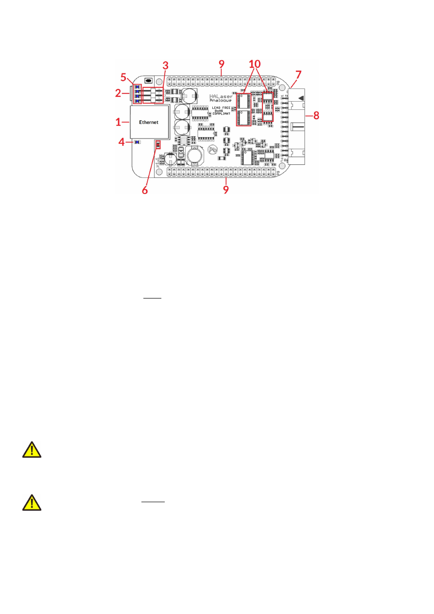
6.2 E1701A Analogue Laser Scanner Controller Baseboard
The E1701A Analogue Laser Scanner Controller Baseboard provides following connectors and interfaces:
1. Ethernet – for communication with the host system, marking information are submitted via this path
2. USB – via microUSB connector for providing BeamConstruct PRO license to host system and
optionally for submitting marking data from host to E1701A card (in case Ethernet is not used)
3. Power – connect with power supply +- 15V DC
4. Power LED – lights when power is available
5. User LEDs – show operational and error states of card
6. Laser LED – shows modulation state of laser
7. microSD-card (on bottom side) – storage place for firmware and extended configuration file, can be
used to upgrade firmware, to change the card's IP and other things more
8. Laser/Scanner signals – white 26 pin laser and scanner output connector which provides analogue
scanner signals as well as laser and marking control IOs
9. Extension connectors – extension boards can be placed below of E1701A Baseboard in order to add
some more functionality and hardware interfaces to the board
10. DAC heatsinks
6.2.1 Ethernet
For a description of usage and configuration of Ethernet interface please refer to related section about
E1701D's Ethernet interface above.
6.2.2 USB
This is a standard miniUSB-connector for connection of the board with the host system. It is used to retrieve
BeamConstruct PRO license and optionally to send marking data to the card. When USB is used for sending all
scanner and laser data, Ethernet cable does not need to be connected.
PLEASE NOTE: USB 2.0 is much slower than a standard 100 Mbit Ethernet connection, so expect slower
execution in case of complex marking data!
Required device driver is installed together with installation of the HALsetup software package (Windows) or
comes with operating system by default (Linux). E1701A card appears as COM-interface on Windows using any
free number for the port. With Linux it appears as /dev/ttyACMx where "x" is any number. These numbers are
provided by the operating system automatically.
PLEASE NOTE: this connection can not be used to power E1701A scanner controller. It may boot up and react
on control commands from host PC but it will not emit any signals at analogue output connectors! A separate
power supply via +-15V is mandatory in order to operate E1701A controller. For details about this power
supply please refer to following section.
35
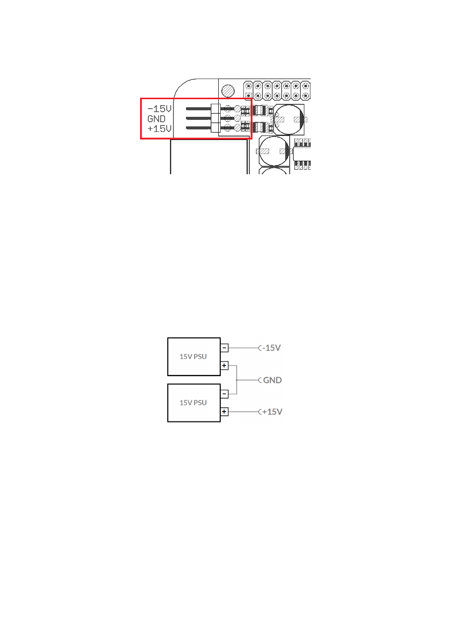
6.2.3 Power
Power supply for E1701A scanner controller board is done via 6 pin header on upper left corner of the board.
Here pairs of pins belong to same power level. An a
ppropriate fuse for circuit protection must be provided by the
external equipment:
Power has to be supplied via this connector by connecting to a bipolar power supply with a maximum voltage of
+-15V DC, max +/- 0.15V tolerance and 1.5A (stabilised and smoothed). Do not apply voltages in excess of 15V
or with inverted polarity to this input. The DC power supply must be grounded.
To avoid the boards components heat up more than necessary, the power input can be limited:
•
when XY outputs operate with +-5V, voltage of +-8V is enough for proper operation
•
when XY outputs operate with +-10V, voltage of +-13V is enough for proper operation
Operating E1701A with a lower voltage than the maximum of +-15V can not only help to keep the board cooler
but also saves power during operation.
To avoid high frequency interferences from other electrical equipment or from within the power supply, it is
recommended to place a ferrite bead at the cable close to the board. Please also check for correct shielding in
respect to the equipment the E1701A card is used within.
When there is no single power supply available which provides +-15V outputs, two separate 15V power
supplies can be used too:
Positive output of the first power supply and negative output of the second one need to be connected with each
other and form the centre ground connector. The remaining negative output of the first and positive output of
the second power supply then are the -V and +V output.
6.2.4 Power LED
For a description of Power LED please refer to related section in description of E1701D controller above.
6.2.5 User LEDs
For a description of User LEDs please refer to related section in description of E1701D controller above.
36

6.2.6 Laser LED
For a description of Laser LEDs please refer to related section in description of E1701D controller above.
6.2.7 microSD-Card
For a description of microSD card, its usage, configuration possibilities, firmware updates and others please
refer to related section in description of E1701D controller above.
6.2.8 Laser/Scanner Signals
The white 26 pin connector provides several signals to be used to control two galvos of a scanhead and a laser
source. The connector is a white one to avoid confusion when a LP8 Extension Board is used too.
The connector provides following signals:
Upper
Row Of
Pins
Signal
Voltage
Remarks
Lower
Row Of
Pins
Signal
Voltage
Remarks
1
X+
+-5V / +-10V,
max 5 mA
2
X-
+-5V / +-10V,
max 5 mA
3
Y+
+-5V / +-10V,
max 5 mA
4
Y-
+-5V / +-10V,
max 5 mA
5
AOut1
0..5V, max 10
mA
6
GND
AOut1
GND
7
Static
Interlock
Connected
with pin 8
8
Static
Interlock
Connected
with pin 7
9
AOut1
0..5V, max 10
mA
10
GND
AOut1
GND
11
AOut2
0..5V, max 10
mA
12
GND
AOut2
GND
13
AOut3
0..5V, max 10
mA
14
GND
AOut3
GND
15
LaserGate CMOS, 0/5V,
max 14 mA
16
GND
GND
17
do not
connect
18
ExtStart
CMOS, 0/5V
Input
19
5V
5V
20
ExtStop
CMOS, 0/5V
Input
21
do not
connect
22
do not
connect
23
do not
connect
24
GND
GND
25
LaserGate CMOS, 0/5V,
max 14 mA
26
do not
connect
LaserGate provides laser modulation signal, turns on the laser during marks and off during jumps. Outputs
LaserGate at pin 15 and LaserGate at pin 25 are working fully parallel, so the maximum current that can be
pulled out of both together is 14 mA.
Analogue outputs AOut1..AOut3 provide additional analogue control. Outputs AOut1 at pin 5 and AOut1 at pin
9 are working fully parallel, so the maximum current that can be pulled out of both together is 10 mA.
ExtStart expects a CMOS-level input signal in respect to GND and can be used as external trigger signal to start
operations when a HIGH-signal is detected at input pin.
ExtStop expects a CMOS-level input signal in respect to GND and can be used as external stop-signal in order
to stop a running marking operation by using a HIGH-signal at input pin.
Static Interlock at pins 7 and 8 is available to be compatible with ILDA standard.
37
PLEASE NOTE: these outputs are connected statically to each other, means there is no condition where
connection between pin 7 and 8 is interrupted! Thus this connection can not be used for security locks in order
to turn off the laser. Here additional, external security measures are necessary!
6.2.9 Extension Connectors
The two extension connectors on each side of the board can be used to place extension boards with additional
peripheral interfaces between E1701A Baseboard and its underlying processor board. So comparing to
extensions added to E1701D scanner controller (as described in detail above), E1701A baseboard always has
to be placed on top. Thus for extending E1701A the baseboard has to be separated from its processor board (as
described in detail in related section in E1701D description above), then extension board(s) has/have to be
placed on processor board while E1701A baseboard afterwards has to complete this set and needs to be added
on top.
For a more detailed description about how to unmount and mount the boards in order to add extensions, please
refer to related section in E1701D description above
PLEASE NOTE: when placing a new extension board or when adding E1701A board on top:
1.check correct orientation and position of the key pin which is closed in connector
2.place the pins of the extension boards onto the extension connectors exactly
3.move down the extension board by pressing on its extension connectors gently; DO NOT PRESS THE BOARD
ITSELF BUT ONLY THE CONNECTORS!
6.2.10 DAC Heatsinks
The DAC heatsinks at the output lines of E1701A can become quite hot. Normal operation temperature can be
up to 125°C without any damage to the electronics. But for integration of this board it is important to ensure
a) proper air flow and
b) nobody and nothing touches these heatsinks in order to avoid injury or other hardware to be damaged.
To limit temperature at these heatsinks, please refer to section regarding power supply of E1701A above.
6.2.11 Stand-Alone Operation
For a description of Stand-Alone-Operation, it possibilities, usage and configuration please refer to related
section in description of E1701D controller above.
38
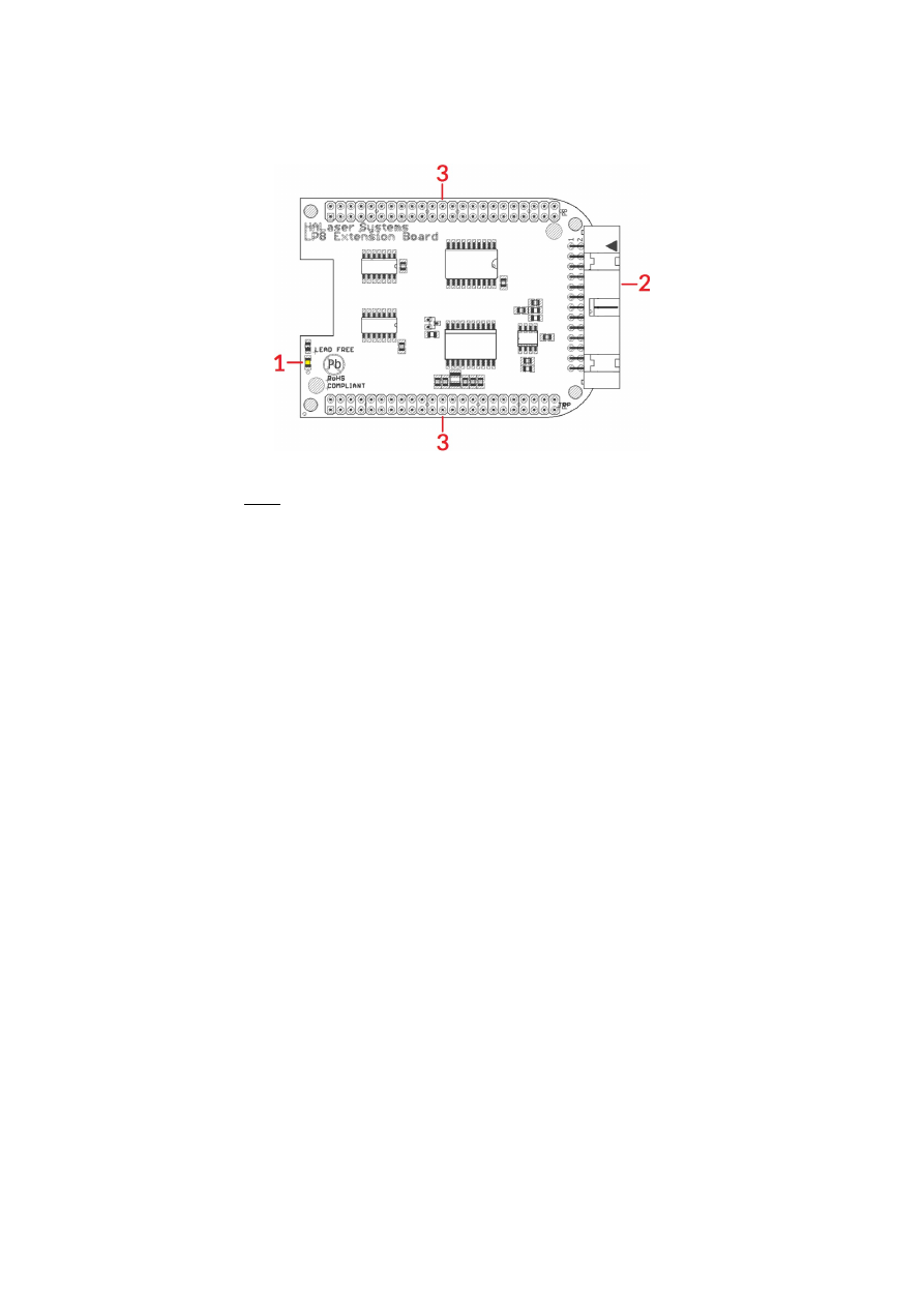
6.3 E1701 LP8 Extension Board
The E1701 LP8 Extension Board can be used with E1701D and E1701A baseboards and provides following
features:
1. MO LED – shows state of Main Oscillator output
2. Laser signals – black 26 pin laser output connector which provides signals for controlling a laser
3. Extension connectors – more extension boards can be placed here in order to add some more
functionality and hardware interfaces to the board, please refer to related section in description of
baseboard above
6.3.1 MO LED
This LED is specific to the Main Oscillator output signal described below. As long as the signal is on (HIGH-
signal at output pin), the LED is turned on.
6.3.2 Laser Signals
The black 26 pin connector provides several signals for controlling a laser source. It can be used e.g. together
with YAG, CO
2
, IPG™, fiber and compatible lasers since it provides additional signals and frequencies these laser
types may require for proper operation. To avoid confusion with similar connector used on E1701D Base board
this connector is black.
The connector provides following signals:
39

Upper
Row Of
Pins
Signal
Voltage
Remarks
Lower
Row Of
Pins
Signal
Voltage
Remarks
1
LP8_0
CMOS, 0/5V,
max 8 mA
2
GND
GND
3
LP8_1
CMOS, 0/5V,
max 8 mA
4
5
LP8_2
CMOS, 0/5V,
max 8 mA
6
5V
5V
7
LP8_3
CMOS, 0/5V,
max 8 mA
8
MO
CMOS, 0/5V,
max 8 mA
Main Oscillator
9
LP8_4
CMOS, 0/5V,
max 8 mA
10
AOut0
0..5V, max 15
mA
Analogue
output
11
LP8_5
CMOS, 0/5V,
max 8 mA
12
13
LP8_6
CMOS, 0/5V,
max 8 mA
14
15
LP8_7
CMOS, 0/5V,
max 8 mA
16
17
LP8
Latch
CMOS, 0/5V,
max 8 mA
18
5V
5V
19
LaserB
CMOS, 0/5V,
max 14 mA
FPK
20
Connected to
pin 21
21
Connected to
pin 20
22
LaserA CMOS, 0/5V,
max 14 mA
PWM,
frequency or Q-
Switch
23
GND
GND
24
25
5V
5V
26
Laser
Gate
CMOS, 0/5V,
max 14 mA
LP8_0...LP8_7 provide parallel 8 bit output signal (e.g. for power control with IPG(tm)/fiber lasers, waveform
selection for SPI(tm) lasers and other).
LP8 Latch pin signals valid output at LP8_0..LP8_7 and AOut0 by submitting a latch pulse of software-
controlled length.
MO can be used to enable main oscillator (e.g. for IPG(tm)/fiber lasers or compatible).
LaserA usage depends on software configuration and control, it is able to output a pulse-width modulated
frequency (e.g. for controlling CO
2
lasers), CW/continuously running frequency (e.g. for fiber lasers) or Q-
Switch signal (e.g. for YAG lasers) in range 25 Hz..20 MHz.
LaserB can be used for emitting a FPK pulse (e.g. for YAG lasers).
AOut0 pin provides unipolar analogue output for controlling e.g. laser power or additional equipment. This
output is directly dependent on LP8_0..LP8_7 output, they are electrically connected and therefore can’t have
different values and can’t be controlled by software independently. So when LP8 outputs are all LOW, AOut0 is
on 0V. When LP8 outputs are all HIGH, AOut0 is 5V.
PLEASE NOTE: output of 5V at AOut0 depends on the used power supply. So in case board is powered via USB
and USB power supply delivers less than 5V, maximum output on AOut0 will be less than 5V too. Here is would
be recommended to use the base board with an external power supply that feeds exactly 5V into it.
6.3.3 Extension Connectors
The two extension connectors on each side of the board can be used to place extension boards with additional
peripheral interfaces. For a description of handling and usage of these connectors please refer above.
1 requires hardware-revision 1.1 or newer
40
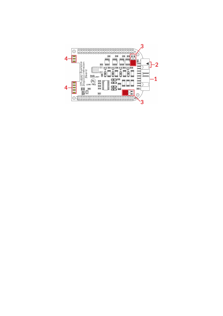
6.4 E1701 Digi I/O Extension Board
The E1701 Digi I/O Extension Board can be used with E1701D and E1701A baseboards and provides following
features:
1. Digi I/O – electrically insulated digital in- and outputs
2. optional inputs for 90 degree phase shifted encoders to be used with marking on-the-fly operations
3. Opto-Configuration – choose operation mode for Digi I/Os
4. Input state LEDs – displaying of HIGH/LOW state of used inputs
In case more extension boards are used on E1701D, Digi I/O extension always has to be placed on top. For
E1701A a specific variant of the Digi I/O extension has to be used which can be stacked and placed below of the
E1701A baseboard which always needs to stay on top.
6.4.1 Digi I/O
The 20 pin connector provides 8 lines for input and 8 lines for output of digital signals that can work on CMOS
level (non-insulated mode) or via opto-couplers (electrically insulated mode with external power supply)
optionally. The operation mode depends on jumper settings described below. The connector is used as follows:
41
Upper
Row Of
Pins
Signal
Voltage
Remarks
Lower
Row Of
Pins
Signal
Voltage
Remarks
1
V
ext
5..24V
Input voltage to
be used in opto-
insulated mode
only
2
GND
ext
GND
External ground
3
DOut0 CMOS, 0/5V
or 0/V
ext
Default level:
LOW
1)
4
DIn0
CMOS, 0/5V
or 0/V
ext
Encoder-input A1
for marking on-
the-fly
5
DOut1 CMOS, 0/5V
or 0/V
ext
Default level:
LOW
1)
6
DIn1
CMOS, 0/5V
or 0/V
ext
Encoder-input B1
for marking on-
the-fly
7
DOut2 CMOS, 0/5V
or 0/V
ext
Default level:
LOW
1)
8
DIn2
CMOS, 0/5V
or 0/V
ext
Second encoder-
input A2 for
marking on-the-
fly
9
DOut3 CMOS, 0/5V
or 0/V
ext
Default level:
LOW
1)
10
DIn3
CMOS, 0/5V
or 0/V
ext
Second encoder-
input B2 for
marking on-the-
fly
11
DOut4 CMOS, 0/5V
or 0/V
ext
Default level:
HIGH
1)
12
DIn4
CMOS, 0/5V
or 0/V
ext
13
DOut5 CMOS, 0/5V
or 0/V
ext
Default level:
HIGH
1)
14
DIn5
CMOS, 0/5V
or 0/V
ext
15
DOut6 CMOS, 0/5V
or 0/V
ext
Default level:
HIGH
1)
16
DIn6
CMOS, 0/5V
or 0/V
ext
17
DOut7 CMOS, 0/5V
or 0/V
ext
Default level:
HIGH
1)
18
DIn7
CMOS, 0/5V
or 0/V
ext
19
V
5V
Board voltage,
to be used only
when not
operating in
insulated mode
20
GND
GND
Board-internal
ground
1)
Please note the wiring scheme and the resulting, inverted logic below: a level of LOW means, the output is
pulled to GND and a load that is connected from V to this pin is turned on. An level of HIGH means, the output is
pulled to V and a properly wired load if turned off.
V
ext
and GND
ext
depend on opto-configuration as described below. In opto-insulated mode (opto-configuration
jumpers not set) external power supply has to be connected to these inputs. Then DIn0..DIn7 and
DOut0..DOut7 work in respect to this external power.
WARNING: When no opto-insulated mode is selected (opto-configuration jumpers are set), do NOT FEED ANY
POWER into V
ext
, this would cause damage to the E1701 board! In this case V
ext
is equal to V (5V) of the board
and GND
ext
is connected to boards ground GND.
Maximum current for every output is 15 mA when internally powered (non-insulated mode), here it is
recommended to use an external power supply.
Maximum current for outputs DOut0..DOut3 is 50 mA when externally powered (V
ext
in insulated mode).
Signal output lines DOut0..DOut7 operate in open collector mode and have to be wired as follows:
42
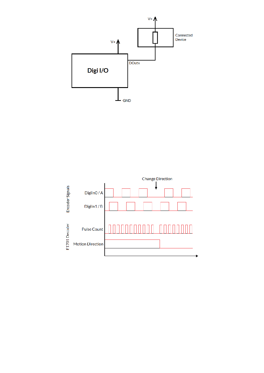
Here “DOutx” symbolises one of the digital outputs DOut0..DOut7. V+ is either V (5V internal, non-insulated
mode) or V
ext
(up to 24V external, insulated mode). GND is either GND (non-insulated mode) or GND
ext
(insulated mode). The internal resistor of the connected device is not allowed to have less than 490 Ohms in
order to not exceed the given current limits.
DOut0..DOut3 provide LOW signal level by default, DOut4..DOut7 provide HIGH level by default. These levels
are valid immediately on power-up of the card.
6.4.1.1 Marking On-The-Fly Signals
Digital inputs 0 and 1 can be used as position encoder signal inputs for marking on-the-fly applications. Here 90
degree phase-shifted input pulses are expected signalling motion direction and position change:
When these pulses are generated from a motion stage that moves the working piece, the resulting position
information is used in marking on-the-fly mode to correct the marking positions accordingly. Resulting from
that, marking will follow motion as far as available scanhead range and working area allows it.
The pulses generated out of the encoder signals have to be multiplied with a factor reflecting the resolution of
the used encoder. To set up and adjust a marking on-the-fly-system properly, following steps have to be
performed:
1. Connect encoder signals A1 and B1 to DigIn0 and DigiIn1 and configure E1701 controller for encoder
usage (either from within BeamConstruct or via programming interface as described below)
2. Mark a square without any encoder signals feed into the controller
3. When the square does not have exact size and/or is distorted, modify correction table and/or gain
settings
4. Mark the same square with a slow motion (using encoder pulses)
43

5. When the square is damaged (means open on one side or compressed) the on-the-fly-factor has to be
changed (set to a smaller or higher value)
6. Mark the same square with a fast motion (using encoder pulses)
7. When the square is damaged (means open on one side or compressed) the on-the-fly-factor has to be
changed (set to a smaller or higher value)
The on-the-fly-factor controls the strength of compensation and is the relation between speed of external
device/encoder pulses and card-internal compensation calculation. When this factor is wrong, the marking
results are distorted. For a square (as recommended to be used in calibration steps above) following results are
imaginable:
The left drawing shows an over-compensated system, here the internal compensation is too strong, the factor is
too big. The right drawing shows an under-compensated set-up, here the factor is too small causing a too weak
compensation. Only when marking result is really a square, the on-the-fly-factor is correct.
When “tune”-flag 2 is set, a second encoder can be used for 2D marking on-the-fly applications (requires
firmware 25 or newer). In this mode digital inputs 0 and 1 (encoder inputs A1 and B1) correspond to X axis and
on-the-fly factor for X direction. Additionally digital inputs 2 and 3 (encoder inputs A2 and B2) correspond to Y
axis and on-the-fly factor for Y direction. Operation principle is the same as for 1D on-the-fly described above:
the incremental values received from the encoders for X and Y are added to the current X and Y coordinates to
be marked. Procedure for adjusting the encoder factor is also the same, here it is recommended to perform this
operation for X and Y movements separately and finally try both motion directions together.
6.4.2 Opto-Configuration
Using these jumpers the operation mode for digital I/Os 0..7 can be chosen. When they are set, the opto-
couplers are powered internally. In this mode it is not working in opto-insulated mode and I/Os are using CMOS
level signals.
When they are not set, external power and ground has to be provided at 20 pin connector (as described above)
and these digital I/Os are working in electrically insulated, opto-coupled mode.
6.4.3 Input State LEDs
These 8 yellow LEDs show the state of corresponding 8 digital inputs. As long as a HIGH signal is detected on an
input, the related LED is turned on.
44
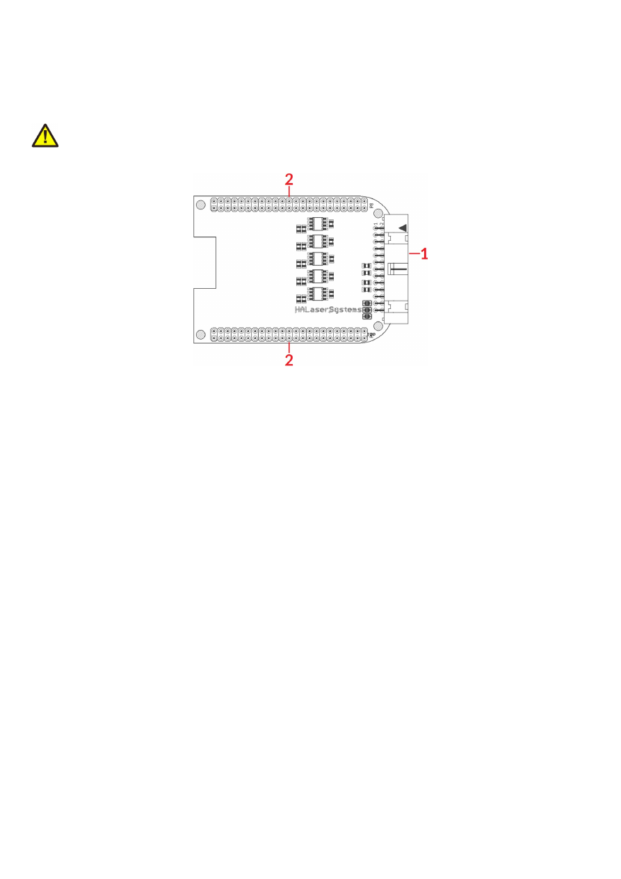
6.5 E1701 Secondary Head Extension Board
The E1701 Secondary Head Extension Board can be used up to three times with the same E1701D Baseboard
to have a scanner controller system with up to four heads connected. These additional scanheads work fully
parallel to the primary scanhead of E1701D baseboard.
PLEASE NOTE: This board can not be used together with E1701A baseboard!
It provides following features:
1. XY2-100 or XY3-100 signals for scanhead
2. Extension connectors – more extension boards can be placed here in order to add some more
functionality and hardware interfaces to the board, please refer to related section in description of
baseboard above
6.5.1 Scanner Signals
The white 26 pin connector provides XY2-100-compliant signals to be used to control up to three galvos of a
scanhead. It can be connected to an XY2-100 compatible scanner system directly and without further
modifications when a 1:1 connection to a D-SUB25 connector is used. The connector is a white one to avoid
confusion when a LP8 Extension Board is used too.
The connector provides following signals:
45

Upper
Row Of
Pins
Signal
Voltage
Remarks
Lower
Row Of
Pins
Signal
Voltage
Remarks
1
CLK-
XY2-100- /
XY2-100-E-
compatible
signals
2
CLK+
XY2-100- /
XY2-100-E-
compatible
signals
3
SYNC-
4
SYNC+
5
X-
6
X+
7
Y-
8
Y+
9
Z-
10
Z+
11
12
13
14
15
16
17
do not
connect!
18
do not
connect!
19
do not
connect!
20
GND
GND
XY2-100- /
XY2-100-E-
compatible
signals
21
GND
GND
XY2-100- /
XY2-100-E-
compatible
signals
22
GND
GND
23
do not
connect!
24
do not
connect!
25
do not
connect!
26
do not
connect!
Comparing to E1701D Baseboard this connector does not provide any laser signals (like LaserGate, LaserA or
LaserB). Since this scanner output works completely parallel to the one from E1701D Baseboard it has to be
used together with the same laser using beam splitters.
When operated in XY3-100 mode, the related signals are provided at the white 26 pin connector. It can be
connected to an XY3-100 compatible scanner system directly and without further modifications when a 1:1
connection to a D-SUB25 connector is used. The connector is a white one to avoid confusion when a LP8
Extension Board is used too.
The connector provides following signals:
Upper
Row Of
Pins
Signal
Voltage
Remarks
Lower
Row Of
Pins
Signal
Voltage
Remarks
1
A-
XY3-100-
compatible
signals
2
A+
XY3-100-
compatible
signals
3
B-
4
B+
5
C-
6
C+
7
D-
8
D+
9
10
11
12
13
14
15
16
17
do not
connect!
18
do not
connect!
19
do not
connect!
20
GND
GND
XY2-100- /
XY2-100-E-
compatible
signals
21
GND
GND
XY2-100- /
XY2-100-E-
compatible
signals
22
GND
GND
23
do not
connect!
24
do not
connect!
25
do not
connect!
26
do not
connect!
46

Comparing to E1701D Baseboard this connector does not provide any laser signals (like LaserGate, LaserA or
LaserB). Since this scanner output works completely parallel to the one from E1701D Baseboard it has to be
used together with the same laser using beam splitters.
6.5.2 Extension Connectors
The two extension connectors on each side of the board can be used to place extension boards with additional
peripheral interfaces. For a description of handling and usage of these connectors please refer above.
47
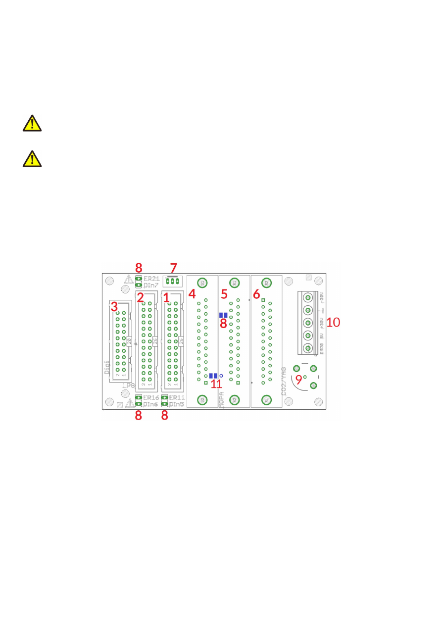
6.6 E1701dock Extension Board
The E1701dock is an expansion board which either can be mounted on very top of the E1701 (using hex-stands
or distance bolts) or which can be mounted near to it (e.g. by using a second E170Xbase). It has to be wired with
simple 1:1 flat-belt cables to the E1701 controller card. Dependent on which extension boards are available,
the E1701dock provides some easy to use interfaces for connecting external equipment without the need to
have own, complex wiring. Or in other words: when E1701dock is used, it acts as some kind of breakout-board,
lasers and scanheads can be connected quite easy, only a few 1:1 cables need to be plugged.
PLEASE NOTE: prior to using the E1701dock, please ensure the pinout of the connectors (as described below)
really fit to your specific variant of your used laser. Elsewhere irreversible damage are possible at laser and/or
scanner controller card.
PLEASE NOTE: when using the laser and/or digital signals (from LP8 or Digi IO extension board) in parallel, you
need to ensure they are not used twice, out of both connectors. This may otherwise result in an undefined and
unwanted behaviour as they work parallel and can’t be switched separately. When a parallel usage is intended,
please double-check the current consumption of connected devices as the total current that can be provided by
these lines does not double but is the same total value for two connections then. Exceeding the total maximum
allowed current of a E1701-signal may cause an irreversible damage to the controller otherwise.
6.6.1 E1701dock Connectors
On top side the E1701dock provides the following connectors:
1.
E1701D baseboard connector
This connector has to be wired with a 1:1 connection to the E1701D baseboard (laser and scanner
connector as described in section “6.1.9 Laser/Scanner Signals”)
PLEASE NOTE: this connector does not fit to the ILDA interface connector of E1701A electrically and
is not allowed to be used with it!
2.
E1701A/D LP8 connector
This connector has to be wired with a 1:1 connection to the LP8 extension boards interface (as
described in section “6.3.2 Laser Signals”); in case additional signals of the LP8 extension need to be
used elsewhere, a flat-belt cable can be used that comes with three IDC-plugs on it. Then one plug can
be connected to the LP8 extension board, one to the E1701dock and the third one to some additional
hardware making use of this interfaces signals. In this case please ensure no signals are double-used
and no short-circuits are caused on input lines, otherwise the controller card, the E1701dock and/or
the connected hardware may be damaged irreversibly!
48
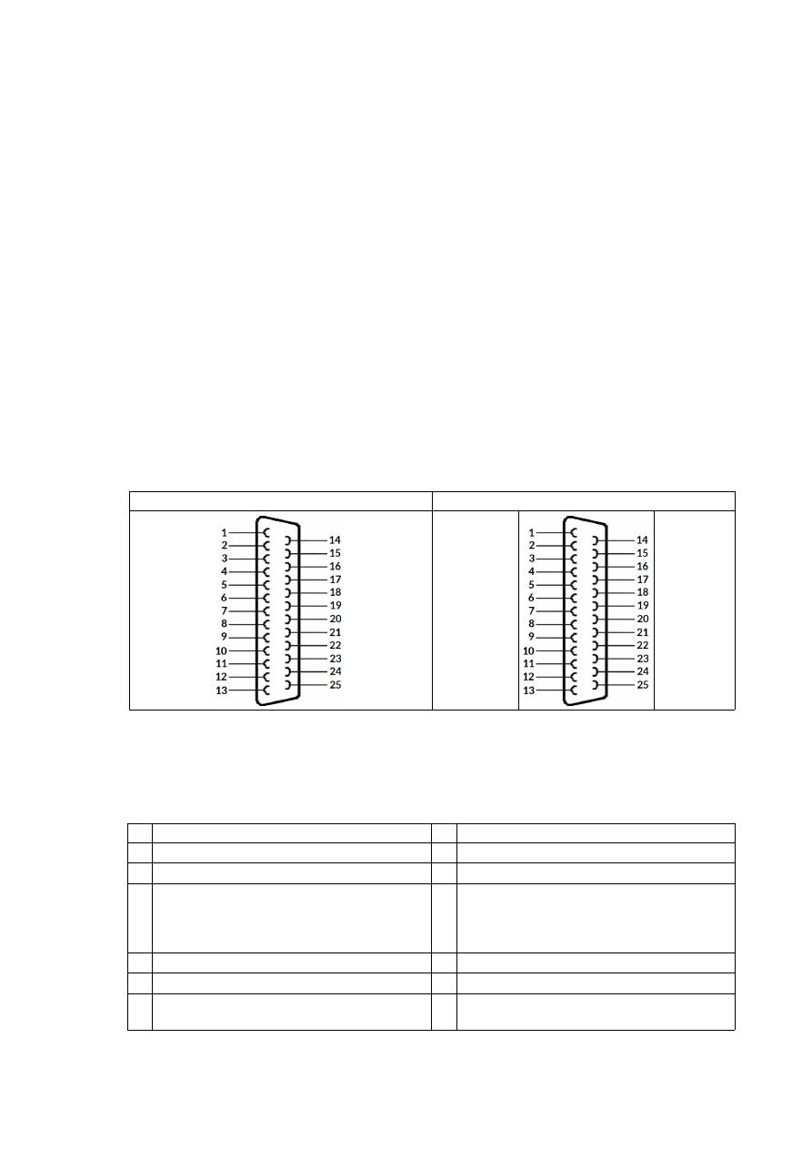
3.
E1701A/D Digi I/O connector
This connector has to be wired with a 1:1 connection to the Digi IO extension boards interface (as
described in section “6.4.1 Digi I/O”); in case additional signals of the Digi I/O extension need to be used
elsewhere, a flat-belt cable can be used that comes with three IDC-plugs on it. Then one plug can be
connected to the Digi IO extension board, one to the E1701dock and one to some additional hardware
making use of this interface. In this case please ensure no signals are double-used and no short-circuits
are caused on input lines, otherwise the controller card, the E1701dock and/or the connected
hardware may be damaged irreversibly!
The Digi I/O connector needs to be wired only in case
- a MOPA laser is connected and at least one of the alarm feedback signals is used or
- A YAG/CO
2
laser is connected and the shutter control signal is used
PLEASE NOTE:
depending on the connected laser and the jumpers (8), some of the digital inputs are
used from within the E1701dock! In this case the related signals should not be used for anything else,
otherwise the controller card, the E1701dock and/or the connected hardware may be damaged
irreversibly by a short-circuit! For more details please refer to the pinout of the laser connectors (5 and
6) and the description of the jumpers (8) below.
4.
XY2-100/XY3-100 connector
In case the E1701dock is used with the E1701D controller card, this interface can be used to connect a
XY2-100/XY3-100 scanhead directly. Here only a 1:1 D-SUB25 cable is needed. On this connector
both, the XY2-100/XY3-100 signals as well as the optional power from the screw terminal (10) are
provided. When a scanhead does not support power supply via the D-SUB25 cable, the power input at
the screw terminal (10) can be left unused. This connector provides the standard pinout for
XY2-100/XY3-100 connectors so that all compliant scanheads can be connected directly:
XY2-100 pinout
XY3-100 pinout
CLK-
SYNC-
X-
Y-
Z-
+V
+V
GND
-V
-V
CLK+
SYNC+
X+
Y+
Z+
+V
GND
GND
-V
A-
B-
C-
D-
E-
+V
+V
GND
-V
-V
A+
B+
C+
D+
E+
+V
GND
GND
-V
5.
MOPA laser connector
This connector of the E1701dock can be used with most MOPA/fiber lasers such as IPG YLP interface
types G (without SPI serial interface and pin 12 alarm signal), E (without APD indexing), D, D1, B, B1,
MaxPhotonics MFP, JPT YDFLP, Raycus RFL-PMX, Raycus RFL-PQB, GZTech YFPN series and
compatible laser types. Connection between E1701dock and laser is done mainly via a 1:1 D-SUB25
cable. The connector provides the following pinout:
Pin Description
Pin Description
1 LP8_0 laser power signal, CMOS, max 8mA
14 GND
2 LP8_1 laser power signal, CMOS, max 8mA
15 Not connected
3 LP8_2 laser power signal, CMOS, max 8mA
16 DIn6 laser alarm pin 16, available at DIn6 of
Digi I/O extension only when jumper
„DIn6/ER16“ is set (refer to description
below)
4 LP8_3 laser power signal, CMOS, max 8mA
17 Not connected
5 LP8_4 laser power signal, CMOS, max 8mA
18 MO main oscillator signal, CMOS, max 8mA
6 LP8_5 laser power signal, CMOS, max 8mA
19 LaserGate power amplifier signal, CMOS, max
14mA
49

7 LP8_6 laser power signal, CMOS, max 8mA
20 LaserA 5V pulse repetitive signal, CMOS, max
14mA
8 LP8_7 laser power signal, CMOS, max 8mA
21 DIn7 laser alarm pin 21, available at DIn7 of
Digi I/O extension only when jumper
„DIn7/ER21“ is set (refer to description
below)
9 LP8 Latch laser power latch, CMOS, max 8mA 22 LaserB used to switch the pilot laser, CMOS,
max 14mA
10 GND
23 Emergency input, connected to screw
connector (10), has to be pulled to HIGH for
different laser types to enable operation
11 DIn5 laser alarm pin 11, available at DIn5 of
Digi I/O extension only when jumper
„DIn5/ER11“ is set (refer to description below)
24 Not connected
12 Not connected
25 Not connected
13 Not connected
The signals on this connector are available only when LP8 extension and optionally Digi I/O extension
is used.
6.
YAG/CO
2
laser connector
This is a connector for direct connection to laser. A connection can be established using a standard 1:1
D-SUB-cable. This connector provides the following pinout which is typically to most common YAG or
CO
2
lasers:
Pin Description
Pin Description
1 Not connected
14 Not connected
2 Not connected
15 Not connected
3 GND
16 Not connected
4 Emergency input, connected to screw
connector (10) and has to be pulled to HIGH
for different laser types to enable operation
17 GND
5 GND
18 GND
6 GND
19 GND
7 Shutter control, this pin is connected to
DOut7 of the Digi IO extension
20 LaserB first pulse killer signal (FPK/QKILL for
YAG lasers) or pilot laser output (for CO2
lasers), CMOS, max 14mA
8 GND
21 AOut1 power control, analogue signal in range
0..10V, max 15mA
9 AOut0 frequency control, analogue signal in
range 0..5V, max 15mA; this signal is
hardware-divided by 2 comparing to the
original AOut0
22 LaserA 5V output, CMOS, max 14mA
10 GND
23 MO used to switch the pilot laser, CMOS, max
8mA
11 GND
24 LaserGate non-inverted/high-active laser-on
signal, CMOS, max 14mA
12 LaserGate inverted/low-active laser-on signal,
CMOS, max 40mA
25 LaserA negative +-5V output of differential
PWM signal (PWM-, also connected to shield
of BNC-connector/9)
13 LaserA positive +-5V output of differential
PWM signal (PWM+, also connected to core of
BNC-connector/9)
The signals on this connector are available only when E1701D and/or LP8 extension and optionally Digi
I/O extension is used.
7.
Start/Stop input connector
50

This connector can be used only together with E1701D controller board and provides easy access to
the ExtStart and ExtStop input pins (as described in section “6.1.9 Laser/Scanner Signals”). The
connector requires a JST PH3P type plug and comes with following pinout:
1 2 3
1 – ExtStart input
2 – ExtStop input
3 - +5V output to be used with ExtStart and ExtStop
8.
MOPA alarm signal jumpers
These jumpers can be set when a MOPA laser is connected via (5) and the alarm feedback signal of this
laser has to be used. For each of the lasers alarm lines that is intended to be read back, the related
jumper has to be set (for details please refer to the pinout of connector 5 above and the manual of your
laser).
Starting with hardware version 1.4 a fourth jumper is available for these laser types that provide an
other error signal via pin 12 of the laser connector. This jumper is a solder jumper which can be found
on bottom side of the E1701dock (marked in blue in image above) and which is named as “ER12 DIn4”.
PLEASE NOTE: when a jumper is set here, the related digital input of the Digi IO extension can’t be
used as input any more! Doing so can cause a short-circuit and may damage the scanner controller
card, the E1701dock and/or the external equipment feeding a signal into DIn5/DIn6/DIn7.
Reading back the laser alarm signals requires the Digi IO extension
9.
BNC-connector for PWM/tickle-signal
It provides a differential +-5V LaserA signal which is also available as PWM+/PWM- at the D-SUB25
connector (pins 13 and 25 of connector 6) and which can be used for all PWM-controlled lasers such as
YAG or CO
2
10.
Power supply and enable signal connector
This connector can be used to supply power to a connected XY2-100/XY3-100 scanhead (E1701D
only) and to apply an enable signal to a connected laser (E1701A and E1701D). It has following pinout:
Pin Name Description
5
-30V
Power supply to scanhead, to be used only with E1701D controller board, is directly
connected to pins 9, 10 and 22 of (4); this input voltage does
NOT
supply the controller
board
4
GND
Common and scanhead ground, is directly connected to pins 11, 23 and 24 of (4)
3
+30V
Power supply to scanhead, to be used only with E1701D controller board, is directly
connected to pins 12, 13 and 25 of (4); this input voltage does
NOT
supply the
controller board
2
5V
5V output from scanner controller card, can be used e.g. to feed EMRG input (e.g. via
contact of a relay). Please note: The “5V” pin of this screw connector is not allowed to be
used for supplying power to any other peripherals.
1
EMRG Emergency/enable input for lasers, this pin is directly connected to pin 4 of YAG/CO
2
connector (6) and pin 23 of MOPA connector (5).
51
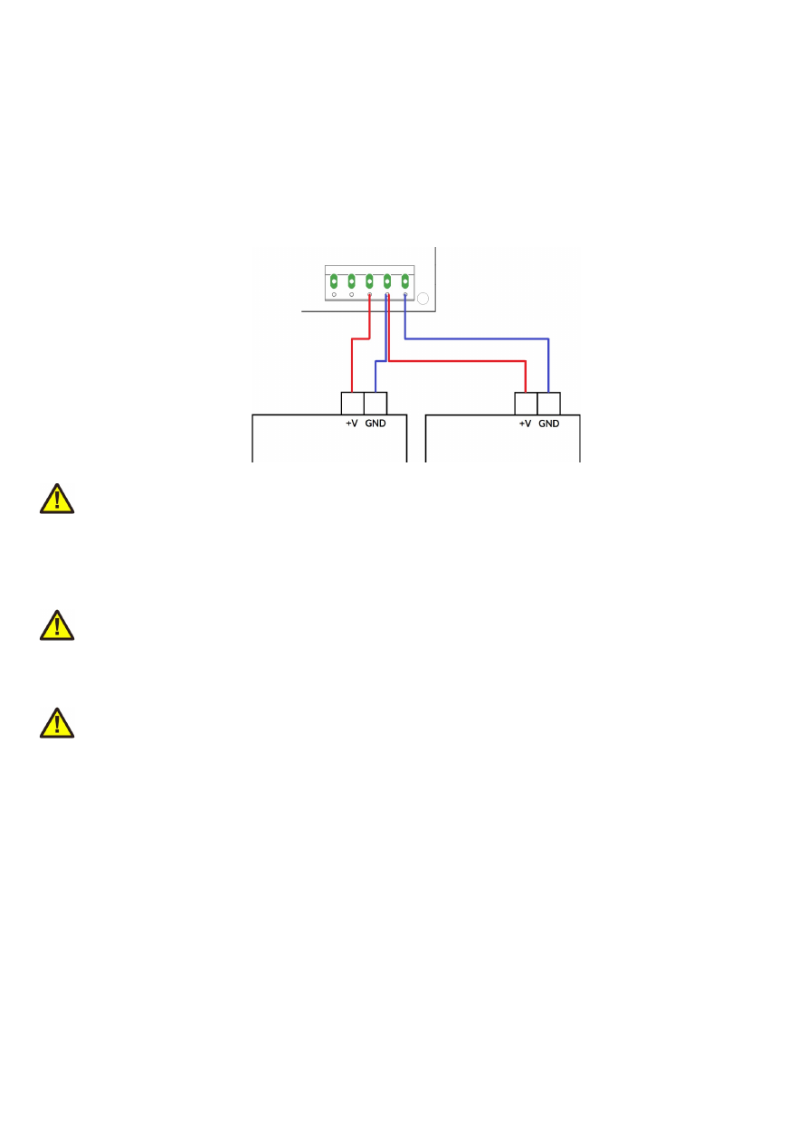
In case the three inputs 3, 4 and 5 are connected to a bipolar power supply providing +-12..+-30V to
power the connected scanhead, the input voltage is feed to the scanhead directly via the
XY2-100/XY3-100 connector but not to the scanner controller card. Here the input voltage has to be
equal to the voltage required by the scanhead (typically +-15V or +-24V). Power supply needs to
provide 1A plus current required for connected scanhead.
When no power supply with symmetric/bipolar outputs is available, it is possible to combine two
standard power supplies. Here GND of the first power supply has to be connected with +V of the
second power supply and with the GND-screw-connector of E1701dock according to following
scheme:
ATTENTION: When connecting wires to the screw terminals, do not transmit any force to the PCB
where the green connector is soldered at! While screwing tight the wires, hold the connector by hand
to catch the force but
do not hold the PCB only!
11. Starting with hardware version 1.4, on bottom side (marked in blue) there is a solder jumper “JP17”
which applies +5V to pin 17 of the MOPA laser connector when closed. This jumper should be closed
ONLY when the connected laser expects a voltage input at this pin in order to operate some internal
functions.
ATTENTION: Closing this pin when the connected laser does not expect this voltage input may cause
irreversible damage to the hardware!
Right beside the solder jumper there is a pinhole which can be used to solder in a wire
when the solder
jumper is not closed
. This pinhole, named as P17, is directly connected to pin 17 of the MOPA D-
SUB25 connector. It can be used to apply any other, custom signal to that pin (depending on what the
laser expects here).
ATTENTION: applying any other signal to P17 while JP17 is closed may cause a short circuit with the
5V rail of the controller and may cause irreversible damage to the hardware!
When you are unsure about the usage of the JP17 solder jumper and/or the P17 wire soldering point,
please contact HALaser Systems first!
6.6.2 E1701dock Wiring
The E1701dock can be mounted on top of a E1701-stack using hex-stands or distance bolts like shown in
picture below. There E1701D is mounted on an E170Xbase (optional) to make use of a DIN-/C45-rail while the
E1701dock is placed on very top. Connection between E1701 controller and its extension boards is done via
short, 1:1 flat belt cables:
52
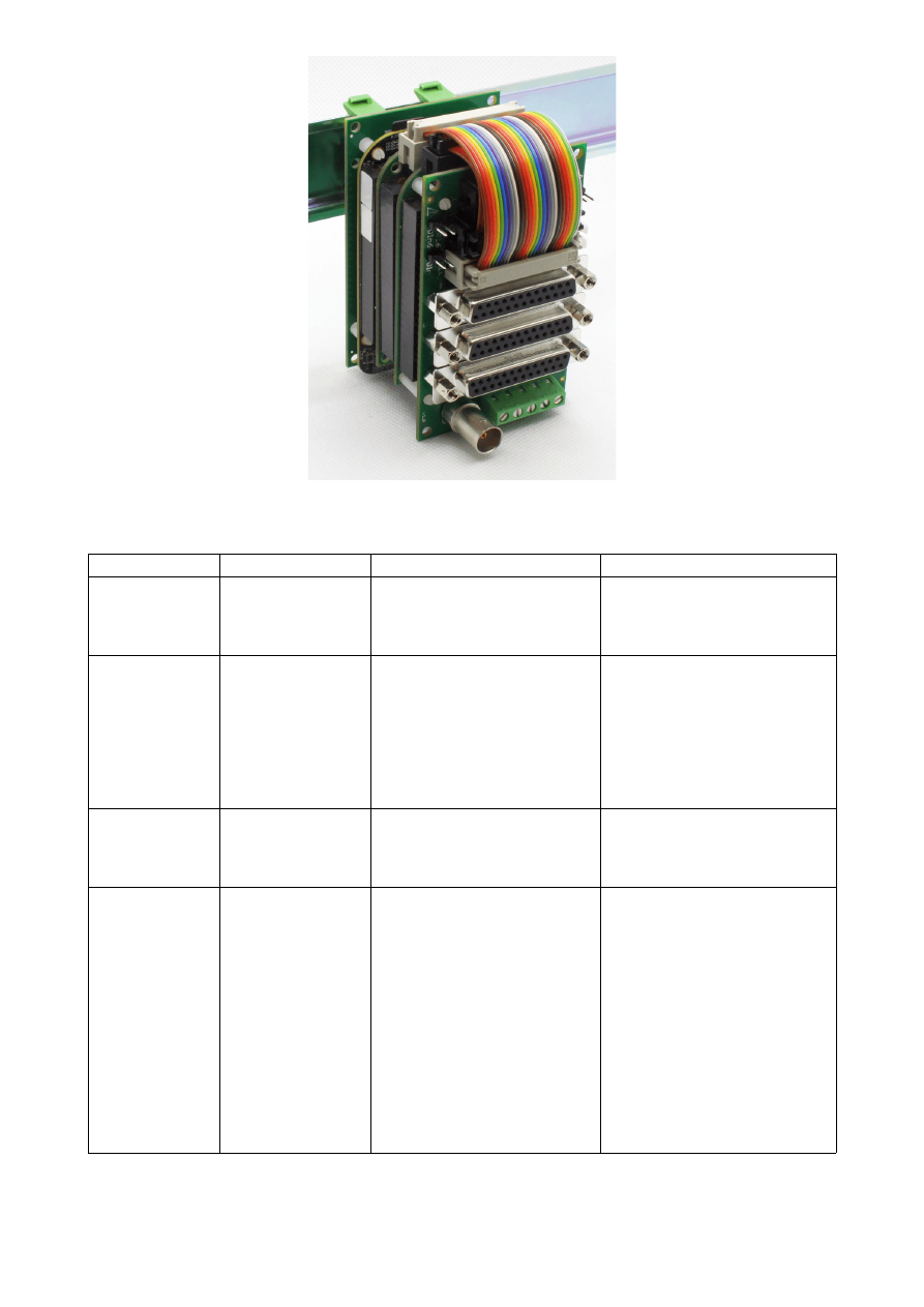
Following all possible configurations are listed including the flat-belt cables that are needed for connection to
E1701dock, given cable lengths are valid when E1701dock is placed on top:
Configuration
Supported Lasers
Wires E1701A
Wires E1701D
Baseboard only
CO
2
/YAG/all PWM-
driven laser types
Not supported
•
1x 1:1 26-pin flat-belt
cable, 5 cm length from
baseboard to E1701dock
(white connectors)
Baseboard plus
LP8 Extension
Fiber/MOPA/CO
2
/
YAG/all PWM-driven
laser types
•
1x 1:1 26-pin flat-belt
cable, 4,5 cm length from
LP8 Extension to
E1701dock
•
1x 1:1 26-pin flat-belt
cable, 4,5 cm length from
LP8 Extension to
E1701dock
•
1x 1:1 26-pin flat-belt
cable, 7,5 cm length from
baseboard to E1701dock
(white connectors)
Baseboard plus
Digi I/O Extension
XY2-100 output on
D-SUB25
Not supported
•
1x 1:1 26-pin flat-belt
cable, 6,5 cm length from
baseboard to E1701dock
(white connectors)
Baseboard plus
Digi I/O Extension
plus
LP8 Extension
Fiber/MOPA with
error feedback,
CO
2
/YAG/all PWM-
driven laser types
•
1x 1:1 20-pin flat-belt
cable, 3,5 cm length from
Digi I/O Extension to
E1701dock (only needed
when MOPA error
feedback is required)
•
1x 1:1 26-pin flat-belt
cable, 6 cm length from
LP8 Extension to
E1701dock
•
1x 1:1 20-pin flat-belt
cable, 3,5 cm length from
Digi I/O Extension to
E1701dock (only needed
when MOPA error
feedback is required)
•
1x 1:1 26-pin flat-belt
cable, 6 cm length from
LP8 Extension to
E1701dock
•
1x 1:1 26-pin flat-belt
cable, 9 cm length from
baseboard to E1701dock
(white connectors)
53
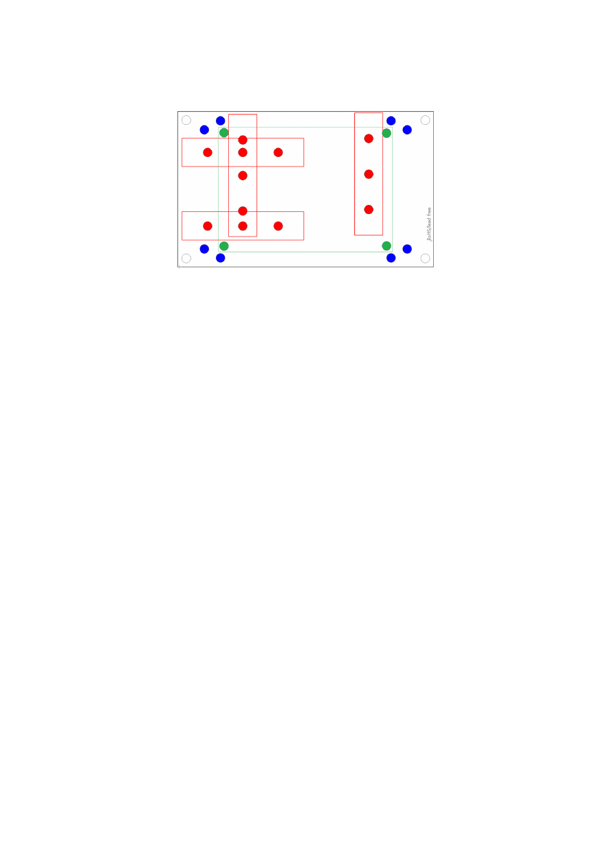
6.7 E170Xbase
The E170Xbase extension is a mounting help for easy installation on DIN rails/C45 rails and other possibilities
of mechanical integration into machines:
RED
– mounting positions for DIN/C45 rail locks/DIN/C45 rail adapters (bottom side). Pairs of locks can be
mounted in one of 2 possible orientations. Here locks of type Phoenix Contact 1201578 or similar can be used.
With these locks the board then can be clamped on a DIN/C45 rail.
BLUE
– mounting holes for the E1701A or E1701D scanner controller card on top of the E170Xbase in one of
two possible orientations. These holes are symmetrically arranged so that the board can be mounted by 180
degrees rotated. Here hex stands/distance bolts with M3 threads (or similar) can be screwed in where the
controller card is mounted on top.
GREEN
– optional; mounting holes for a HALdrive converter board (top side) instead of an E1701X scanner
controller card, here hex stands/distance bolts with M2 threads (or similar) can be screwed in where the
HALdrive is mounted on top.
Mounting procedure for E170Xbase:
1. Identify suitable positions (
RED
) for two DIN/C45 rail locks and mount them on bottom side (two or
three screws from top side into the lock on bottom)
2. Mount hex-stands or distance bolts in at least four of the given mounting holes (
BLUE
).
3. Mount E1701A or E1701D on top of these hex-stands/distance bolts
4. Clamp the board on your DIN/C45 rail
Without the DIN/C45 rail clamps the board also can be used as top-cover for the E1701A or E1701D.
54

7 Quick Start into E1701A/D
Following a few steps are described that give users the possibility to quick start into usage of E1701A/D
scanner controller. It makes use of BeamConstruct and the (slow) USB connection. For this quick start manual it
is assumed correct wiring of the controller is already done according to the description above. For more
detailed information about BeamConstruct usage please also refer to quick start manual from
https://halaser.systems/download/manual_quickstart.pdf
and to full user manual which is available at
https://halaser.systems/download/manual.pdf
To start with E1701A/D controller:
1.
SECURITY CHECK:
The following steps describe how to set up E1701A/D scanner controller card and
how to control laser equipment with them. Thus all laser safety rules and regulations need to be
respected, all required technical security mechanisms need to be available and active prior to starting
with it.
2. Install latest software version from
https://halaser.systems/download.php
– for Windows this package
contains all required drivers, for Linux no separate drivers are needed.
3. Connect E1701A/D controller via USB. For E1701A external +-15V power supply is required (as
described above).
4. Now the Alive-LED should light up and then start blinking after some time. When this does not happen,
please turn power off, check if the microSD-card is placed correctly and then try again.
5. Evaluate the serial interface the controller is connected with – for Windows the Device Manager (can
be found in Control Panel) will list a new COM-port (e.g. “COM3”); for Linux type “dmesg” in console to
find out to which interface it was connected with (typically “/dev/ttyACM0”).
6. Start BeamConstruct laser marking software.
7. Go to menu “Project” “Project Settings...”, then tab-pane “Scanner”.
→
8. Now you can either select “E1701A” as scanner controller card or can go with “E1701D” which is
selected and preconfigured by default. If none of both is selected, please choose the appropriate
scanner controller in the related combo box.
9. Press the “Configure”-button to get into the settings dialogue for E1701A/D plug-in.
10. Enter the serial interface name in field “IP/Interface” (e.g. “COM3” or “/dev/ttyACM0”).
11. Leave everything with “OK”.
12. Draw some geometries as described in “BeamConstruct Quick Start Manual”.
13.
SECURITY CHECK:
Next the scanner controller card will be accessed for the first time. That means it is
opened and initialised and all connected equipment may start working now. Thus it is very important to
ensure all security regulations are met and nobody can be injured and no damage can be caused also in
case laser output or other motion starts spontaneously and unexpectedly!
14. Press “F2” or go to menu “Process” “Mark” to open the mark dialogue.
→
15. Start marking by pressing the yellow button with the laser-symbol
55

8 Command Interface
The commands described in this section require firmware version 12 or later.
When E1701 scanner card is connected via USB and the USB-connection is NOT used for transmitting marking
information, it can be used to send control commands to the card. Some of them are independent of the current
operating mode and some of them can be used only in case the controller is operating in stand-alone mode.
Starting with firmware version 15 control commands can also be sent via Telnet using Ethernet connection.
Here a Telnet-client has to connect to port 23 using the IP of the scanner controller. This Telnet client should
work in passive mode. So when E1701 scanner card is connected via Ethernet and the Ethernet-connection is
NOT used for transmitting marking information, it can be used to send control commands to the card. Some of
them are independent of the current operating mode and some of them can be used only in case the controller
is operating in stand-alone mode.
Such a control command always consists of ASCII-text. An appropriate client has to connect to the serial port
(COMx for Windows and /dev/ttyACMx for Linux where “x” is a number identifying the specific serial interface
or TCP/IP port 23). As soon as the connection is established, commands can be sent to the card. All commands
come with following structure:
cxxxx <parameter(s)>
The commands always start with character “c”. Next four characters identify the command itself. Depending on
the command one or more optional or mandatory parameters may follow. The command always returns with an
"OK" or with an error.
8.1 General Commands
The following commands can be used in all scenarios, they do not depend on a specific operation mode of the
card. Nevertheless it is recommended to not to send commands excessively during card is marking, to not to
influence marking operation.
cvers
"
vers
ion" – return version information of the controller card. This command returns a version string
specifying version of hard- and firmware in style
vFF-H
where “
FF
” is the version of the firmware and “
H
”
specifies the hadware revision of the controller.
cecho <0/1>
"
echo
" – when typing commands in a serial console communicating with the controller, all the typed
characters are echoed, means they are sent back to the host so that a user can see what is typed. This may be an
unwanted behaviour when an application communicates with this interface. Using this command the serial
echo mode can be turned off (parameter 0, only return values are sent back) or on (parameter 1, all data are
sent back). When called with no parameters, the current echo mode value is returned.
Example:
cecho 0
– turn off echo mode
cgbds
"
g
et
b
oar
ds
" – get an identifier value for the connected boards. This command returns a decimal
number which depends on the connected extension boards and can be used to identify them. The returned
value is a sum consisting of the following numbers:
1 – XY2-100/XY3-100 baseboard (E1701D) is available
2 – analogue baseboard (E1701A) is available
256 – LP8 Extension Board is available
512 – Digi I/O Extension Board is available
cglog
"
g
et
log
line" – returns a single logging line. This command has to be called repeatedly until an error is
returned to get logging information from the controller. On each call of this function one logging line is
56

returned. When "
cglog
" isn't used for a longer time it may be possible the internal log-buffer has overrun. In
this case "
cglog
" will not return all log information, previous log data may be overwritten.
cgbsr
"
g
et
b
oard
s
e
r
ial number" – returns the serial number of the card. This number is an unique, internal
value that is used e.g. to identify a controller on host PC when more than one scanner card is used.
8.2 Stand-Alone Control Commands
Following commands are useful in case scanner controller is operating in stand-alone mode where marking data
are loaded from microSD-card using special EPR-fileformat.
cstop
"
stop
" – stop marking as fast as possible. A running marking operation is stopped and LaserGate is
turned off.
chalt <0/1>
"
halt
" – halts or continues the processing and output of marking data. When given parameter is equal
to 1, marking is stopped next time the laser is off but no vector data are dropped. On continue (parameter equal
0) controller continues processing at the point where halt occurred. When marking is stopped with
cstop
the
halt-condition is cleared too, means on next transmission of new marking data they are processed without the
need to explicitly continue operation by calling
chalt 0
.
cstrt
"
st
a
rt
" – start marking operation. This command can be called only when no marking operation is
running and when a valid project (.epr) file was loaded. In this case the currently loaded project is marked once.
ctrig
"
trig
ger" – send an external trigger signal by software. When scanner card is in state "marking" but
waiting for an external trigger, this command releases this trigger. So behaviour is the same like a rising edge on
the ExtStart input of the controller card.
cstat
"
stat
e" – return the current state of the card. This command returns one of the following texts
identifying the operational state:
•
marking
– card is processing some marking data currently, means either actively outputting them or
waiting for an external trigger to start marking
•
stand-alone
– controller is in stand-alone mode
•
idle
– card is waiting and not marking
•
waiting
– a project file was loaded, is ready for execution and waits for a trigger signal (either via
ExtStart input or via command "
ctrig
")
cgtin
"
g
et
t
rigger
in
puts" – get the state of the external input signals. This command is not related to digital
inputs of Digi I/O extension board but provides information regarding signal state of external start and stop. It
returns a value that specifies which of these input signals are currently HIGH:
0 – ExtStart and ExtStop are both LOW
2 – ExtStart is HIGH
4 – ExtStop is HIGH
6 – ExtStart and ExtStop are both HIGH
cscor <idx>
57

“
s
et
cor
rection” - specifies a new index for a previously loaded correction file (see description of
configuration parameter
corrtable
in section “6.1.8 microSD-Card” above). The parameter
idx
can be a
value in range 0..15 and needs to correspond to a previously loaded correction table. The newly set correction
table applies to all vector data which are processed after this call. Thus it is recommended to use it only when
marking operation was stopped – elsewhere it is not predictable how many vector data already have been pre-
calculated with the previous correction table and starting with which vector data the new correction file is
used.
When a
idx
-value is set which corresponds to no correction file data, no more correction is performed on
vector data.
This command requires firmware version 33 or newer.
cgcor
“
g
et
cor
rection” - this command is the counterpart of
cscor
and displays the index number of the
currently used correction file
This command requires firmware version 33 or newer.
clepr <path>
"
l
oad
epr
" – loads an EPR stand-alone file from microSD card for outputting it on next marking
operation. This command can be executed in stand-alone mode only.
When operating in stand-alone mode “idxselect”, the command expects a number as parameter which specifies
the index file to be loaded.
When operating in stand-alone mode “ioselect” or “iohaltedloop”, the command is not supported.
When operating in any other stand-alone mode, the command expects the path to the file to be loaded as
parameter. Since this is the only parameter, no quotes are allowed for the pathname. The pathname itself has to
be in format
0:/filename.epr
where
0:/
specifies the microSD-card and
.epr
is the standard extension of E1701 stand-alone marking data
files (this name is a shortcut for "
E
1701
Pr
ocessing Data"). During loading the ready-for-marking output signal
is turned off and it is turned on only in case the file could be loaded successful (please refer to related section
above).
Examples:
clepr 0:/test.epr
– loads a stand-alone file "test.epr" from microSD card
cgepr
“
g
et
epr
” – returns the name of the currently loaded stand-alone file or an error “no file specified” when
no file is loaded.
cdepr <path>
"
d
elete
epr
" – deletes an EPR stand-alone file and all related, additional files from microSD card. This
command can be executed in stand-alone mode only.
When operating in stand-alone mode “idxselect”, the command expects a number as parameter which specifies
the index file to be loaded.
When operating in stand-alone mode “ioselect” or “iohaltedloop”, the command is not supported.
When operating in any other stand-alone mode, the command expects the path to the file to be delete as
parameter. Since this is the only parameter, no quotes are allowed for the pathname. The pathname itself has to
be in format
0:/filename.epr
where
0:/
specifies the microSD-card and
.epr
is the standard extension of E1701 stand-alone marking data
files (this name is a shortcut for "
E
1701
Pr
ocessing Data"). Deleting is done asynchronously, so the returned
“OK” only verifies the command was accepted. Successful deletion of the file can be assumed after 0,5 seconds.
Examples:
cdepr 0:/test.epr
– deletes a stand-alone file "test.epr" from microSD card. When additional
files
test.dat
(which may contain related dynamic data) and
test.ser
(which may hold serial number
information) exist, they are deleted by this command too.
This command requires a firmware version 43 or newer.
58

ctlxy <x> <y> <z>
“
t
urn on
l
aser at given
XY
Z position” – lets the scanner move to a specific position and turns on the laser as long
as ExtStart is HIGH
This command requires stand-alone mode “auto”. It can be used to turn on the laser as long as the ExtStart input
is at HIGH. So using this function some externally controlled drilling or cutting operations are possible. As
parameter it expects the X, Y and Z coordinate positions to jump to (in unit 26 bits). The sequence of commands
to use this function are as follows:
•
unload the current project file (“e.g. by calling “
clepr 0:/notexist.epr
”)
•
call “
ctlxy
” together with the 26 bit XYZ position the scanner has to jump to the parameters used
→
for jumping are the ones out of the last EPR file executed
•
the state-flag
E170X_CSTATE_SAC_CTLXY
is set
•
the state-flag
E170X_CSTATE_SAC_READY
is set as soon as the scanner has arrived at the specified
XYZ position, this happens together with the output DOut0:
•
wait until DOut0 goes to HIGH this output signals the specified XYZ position was reached and the
→
controller is able to turn on the laser now
•
pull ExtStart to HIGH the laser is turned on within 1 usec at max using the laser parameters out of
→
the last EPR file executed
•
as long as ExtStart is HIGH, the laser is turned on and DOut1 is at HIGH and the state-flag
E170X_CSTATE_SAC_MARKING
is set
•
pull ExtStart to LOW as soon as the laser has to be turned off both DOut0 and DOut1 are pulled to
→
low, the laser is turned off within 1 msec at max and all
E170X_CSTATE_SAC_
-flags are reset
•
now the complete sequence has ended ad the
ctlxy
-command has elapsed. To turn on the laser via
ExtStart again, a new command
ctlxy
has to be issued
Example:
ctlxy 33554432 33554432 33554432
Starts a ctlxy-sequence as described above with the scanner moved to the centre position.
This command requires firmware version 40 or newer.
csbuf <idx> <path>
“
s
et
buf
fer” - this command works similar to the configuration parameter “iobuff” and can be called in
stand-alone modes “ioselect” and “idxselect”. It can be used to preload EPR stand-alone data files into memory
so that they can be accessed faster and without additional accesses of the SD card. The first parameter
<idx>
is mandatory and specifies the slot the EPR file has to be loaded to. Different to parameter “iobuff” where the
slot number is given automatically and where the index value can be in range 1..255, here the slot number and
the index number are always the same and are in range 1..20. So only the first 20 index values can be used
together with this dynamic loading function. When only
<idx>
is given, the loaded file is
0:/<idx>.epr
.
Optionally also a file name
<path>
can be given in format
0:/file.epr
. In this case the given file is loaded to
the slot specified by
<idx>
and can be accessed with the related index number. After every call to
csbuf
the
command
cgbuf
has to be executed repeatedly until it returns -1.
Examples:
csbuf 3
– loads the file
0:/3.epr
from SD-card and stores it in slot number 3 so that it can be accessed
either via “
clepr 3
” (in stand-alone mode “idxselect”) or via a digital input pattern at the Digi I/O Extension
representing a 3 (in stand-alone mode “ioselect)
csbuf 5 0:/markme.epr
– loads the file
0:/markme.epr
from SD-card and stores it in slot number 5 so
that it can be accessed either via “
clepr 5
” (in stand-alone mode “idxselect”) or via a digital input pattern at
the Digi I/O Extension representing a 5 (in stand-alone mode “ioselect)
This command requires firmware version 36 or newer.
cgbuf
“
g
et processed
buf
fer” - returns the index number of the buffer that is currently processed by a
previous call to
cgbuf
. As long as this command returns a value greater than -1, no other calls to
csbuf
are
59

allowed. The returnend number specifies the index/slot number that is currently filled with data. When
cgbuf
returns -1, the loading operation has been finished.
This command requires firmware version 36 or newer.
cjsor <percentage>
“
j
ump
s
peed
o
ver
r
ide” – changes the speeds of all jump speed values by the given factor. Here
parameter
percentage
has to be given in unit 1/100%. The override-value specified by this command remains
active until it is set back to normal value by calling “
cjsor 10000
” or until the controller is rebooted. The
value given here is active for all processed data including host-controlled marking projects and stand-alone files
loaded from microSD card.
This command requires firmware version 25 or newer.
cmsor <percentage>
“
m
ark
s
peed
o
ver
r
ide” – changes the speeds of all mark speed values by the given factor. Here
parameter
percentage
has to be given in unit 1/100%. The override-value specified by this command remains
active until it is set back to normal value by calling “
cmsor 10000
” or until the controller is rebooted. The
value given here is active for all processed data including host-controlled marking projects and stand-alone files
loaded from microSD card.
This command requires firmware version 25 or newer.
cpwor <factor>
“
p
o
w
er
o
verw
r
ite” - this command modifies the actual power by using the given factor (in unit 1/100%).
All operations make use of the changed power until a factor of 10000 is set or until the controller is restarted.
This is true for both, stand-alone applications where an .EPR-file is loaded from microSD-card and for host-
controlled marking operations (via libe1701 or BeamConstruct).
This command influences following methods of setting laser power:
•
pulse width, here user has to ensure the resulting pulse width is smaller than the period of the related
frequency, elsewhere the output will be a continuous signal
•
LP8 laser port
•
AOut0 and AOut1 analogue outputs
cfror <factor>
“
fr
equency
o
verw
r
ite” - this command modifies the actual frequency by using the given factor (in unit
1/100%). All operations make use of the changed power until a factor of 10000 is set or until the controller is
restarted. This is true for both, stand-alone applications where an .EPR-file is loaded from microSD-card and for
host-controlled marking operations (via libe1701 or BeamConstruct).
This command is not available for lasermodes CO
2
or YAG
This function requires firmware version 42 or newer.
cpuor <factor>
“
pu
lse-width
o
verw
r
ite” - this command modifies the actual pulse-width by using the given factor (in
unit 1/100%). All operations make use of the changed pulse-width until a factor of 10000 is set or until the
controller is restarted. This is true for both, stand-alone applications where an .EPR-file is loaded from
microSD-card and for host-controlled marking operations (via libe1701 or BeamConstruct).
This command is not available for lasermodes CO
2
or YAG, there the pulse-width is changed via command
cpwor
.
This function requires firmware version 42 or newer.
cgmtx
“
g
et
m
atri
x
” - return the four elements of the 2x2 output matrix. The members of the matrix are
returned as four integers with a factor of 1000. So returned values of “1200 0 0 1200” are equal to a matrix
1,2 0,0
60

0,0 1,2
Which itself defines a scale factor of 1,2 in both, X and Y direction of the output.
This function requires firmware version 38 or newer.
csmtx <m11 m12 m21 m22>
“
s
et
m
a
t
ri
x
” - set a 2x2 matrix which is used for the global output of the scanner card. This means, the
values applied here influence the whole project which is currently be marked. Such a 2x2 matrix can be used to
modify the X- and Y-scale, the rotation and the X- and Y-slant of the output. The matrix members m11, m12,
m21 and m22 have to be given as integers which represent the matrix elements multiplied by 1000.
As soon as a custom matrix is set via this command, all matrix values out of a loaded EPR file are ignored and
only the matrix-values currently set are used. This includes gain and rotation correction settings which may be
set in such an EPR file.
Example:
csmtx 996 -87 87 996
– rotate the output by 5 degrees; these values are generated out of the
unity matrix {1000, 0, 0, 1000} which was multiplied with the rotation matrix {cos(5)*1000, -sin(5)*1000,
sin(5)*1000, cos(5)*1000}
This function requires firmware version 38 or newer.
cswaf <factor>
Sets a factor in unit bits per mm that is used with all commands that specify some distance or position (such as
cspof
). When this factor is set to a proper value, the given positions/distances can be specified in unit um
instead of bits. When a factor of 1000 is specified, the functionality is reset back to the default behaviour where
position values have to be given in unit bits.
This parameter requires a firmware version 45 or newer.
cspof <x y z>
“
s
et
p
osition
of
fset” – sets a n position offset for the complete output. This function expects three parameters
for the offset to be set in X, Y and Z-direction. The values to be given here are signed 26 bit, means they need to
be in range -33554431..33554432. To reset the offset for one or more directions, a value of 0 has to be set.
Please note: this offset is set prior to the matrix calculations which may be done when a custom output matrix is
set using command
csmtx
. Resulting from that, the matrix calculation also applies to the offset defined here. So
when the matrix e.g. defines a scale factor for the output, the offset values specified here are scaled by the same
factor.
Example:
cspof -16777216 0 0
– shift the output by a quarter of the whole available working area to the
left.
This function requires firmware version 42 or newer.
cstxt <"elementname"> <"text">
"
s
et
t
e
xt
" – set a new text value to an element in currently loaded project. The parameters for this
command both have to be given with quotes ("). Setting a text is possible only for dynamic elements like
Datamatrix barcodes or texts. Here
"elementname"
is the name of the element that has to be modified (this is
the same name like shown in element tree of BeamConstruct) and the new text to be set. The
"text"
itself can
be a format string as used within BeamConstruct when a serial number input element is involved
Example:
cstxt "Barcode 1" "Hello :-)"
- sets a new text "Hello :-)" for the element with name
"Barcode 1"
cgtxt <"elementname">
"
g
et
t
e
xt
" – gets the currently used text value of an element in loaded project. The parameter for this
command has to be given with quotes ("). Getting a text is possible only for dynamic elements like Datamatrix
barcodes or texts.
Example:
cgtxt "Barcode 1"
– gets the text from the element with name "Barcode 1"
61

csser <"elementname"> <cnt>
"
s
et
ser
ial number" – sets a new serial count value to an element in currently loaded project. The
element name for this command has to be given with quotes ("). Setting a new count is possible only for dynamic
elements like Datamatrix barcodes or texts that have a serial number input element assigned. Setting the value
has to be handled with care, here every value can be specified independent if it fits to possibly exiting beat
count values.
Example:
csser "Text 2" 42
– set a new serial number count value 42 for element with the name "Text 2"
cgser <"elementname">
"
g
et
ser
ial number" – gets the current serial count value from an element in loaded project. The
element name for this command has to be given with quotes ("). Getting the count is possible only for dynamic
elements like Datamatrix barcodes or texts that have a serial number input element assigned.
ciser <"elementname">
"
i
ncrement
ser
ial number" – increments the current serial count value of an element according to its
serial number parameters. The element name for this command has to be given with quotes ("). Incrementing
the count is possible only for dynamic elements like Datamatrix barcodes or texts that have a serial number
input element assigned. This function is more secure than forced setting of a new count value with "csser" since
it can't violate the counting rules.
cdser <"elementname">
"
d
ecrement
ser
ial number" – decrements the current serial count value of an element according to its
serial number parameters. The element name for this command has to be given with quotes ("). Decrementing
the count is possible only for dynamic elements like Datamatrix barcodes or texts that have a serial number
input element assigned. This function is more secure than forced setting of a new count value with "csser" since
it can't violate the serial number counting rules.
crser <"elementname">
"
r
eset
ser
ial number" – resets the current serial count value of an element to its start-value (according
to its serial number parameters). The element name for this command has to be given with quotes ("). Resetting
the count is possible only for dynamic elements like Datamatrix barcodes or texts that have a serial number
input element assigned. This function is more secure than forced setting of a value with "csser" since it can't
violate the predefined serial number parameters and automatically uses the correct reset value.
cstim <seconds>
"
s
et
tim
e" – this command sets the system time to the value specified with the parameter. Here the
number of seconds have to be specified that have elapsed since 01.01.1970 at 00:00:00. After sending this
command the controller card operates at the given time. The time value is lost after next power cycle and has to
be set again.
Example:
cstim 1420113600
– set the internal time of E1701 controller to 01.01.2015 12:00:00, here
1420113600 represets the number of seconds that have been elapsed between 01.01.1970 00:00:00 and
01.01.2015 12:00:00
crtim
"
r
etrieve
tim
e" – this command schedules time retrieval from an SNTP server asynchronously. It always
returns with "OK" since the command is scheduled for execution during next working cycles. To use this
command, controller has to be configured with IP, netmask, gateway and SNTP server IP correctly and needs to
be able to access this SNTP server from its position in network. For details please refer to description of
configuration parameters in section about microSD card above.
cgtim
"
g
et
tim
e" – returns the current time of the board in number of seconds that have elapsed since
01.01.1970 at 00:00:00. After powering up the board and before a valid time has been set, this value is
undefined.
62

cftim
"
g
et
f
ormatted
tim
e" – returns the current time of the board as formatted string in style DD.MM.YYYY
hh:mm:ss. After powering up the board and before a valid time has been set, this value is undefined.
cstyr <year>
"
s
et
t
ime
y
ea
r
" – sets the year of the current system time to the value given as parameter. This value
has to be in range 1900..2038
cstmo <month>
"
s
et
t
ime
mo
nth" – sets the month of the current system time to the value given as parameter. This
value has to be in range 1..12 according to the number of the month.
cstdy <day>
"
s
et
t
ime
d
a
y
" – sets the day of the current system time to the value given as parameter. This value has
to be in range 1..28, 1..30 or 1..31 according to the length of the current month. To avoid invalid combinations it
is recommended to set the month (using command
cstmo
) before setting the day.
csthr <hour>
"
s
et
t
ime
h
our" – sets the hour of the current system time to the value given as parameter. This value
has to be in range 0..23.
cstmi <minute>
"set time minute" – sets the minute of the current system time to the value given as parameter. This
value has to be in range 0..59.
cstsc <second>
"
s
et
t
ime
s
e
c
ond" – sets the second of the current system time to the value given as parameter. This
value has to be in range 0..59.
cgsta
"
g
et
s
erial s
ta
te" – this command applies only when working in stand-alone mode with dynamic serial
number data that change on every mark operation. It returns information if the state of serial numbers has
changed and is not yet saved (in this case "pending" is returned) or if they have been saved and therefore do not
get lost when power is turned off now ("saved" is returned in this case).
cssta
"
s
ave
s
erial s
ta
te" - this command applies only when working in stand-alone mode with dynamic serial
number data that change on every mark operation. When it is called, a command to save the current state of
serial numbers is enqueued and will be processed as soon as controller is able to store these data. So when this
command returns with "OK" that doesn't necessarily means the serial number states are saved now. The
current save state still has to be checked by calling
cgsta
after
cssta
has been issued.
crrrr
"
r
eboot" – perform a warm reboot of the hardware and restart the firmware. Reboot is done
immediately, means this command does not return anything but connection to the board will be interrupted as
soon as it has been sent.
This command requires firmware version 19 or newer.
63

8.3 Hardware Commands
These commands can be used to access hardware signals directly. When these hardware outputs are set or
unset while a marking operation is running, they may have no effect as they may be overridden immediately.
Thus it is recommended to execute them only when the controller card is idle and no other operations are in
progress. But also in this case, when a hardware output is set to a specific state, any operation (especially
marking cycle) that is executed afterwards, may override that specific state-changes. Following hardware-
specific commands are supported:
cginp
"
g
et
inp
ut" – get the current state of the digital inputs (in case a Digi I/O extension is available). The
input state is returned as a decimal number representing the bitpattern at the inputs. So when e.g. a value "15"
is returned, this means the lower four inputs are set to HIGH while the upper ones are at LOW level
csout <value>
"
s
et
out
put" – set the state of the digital outputs (in case a Digi I/O extension is available). The output
to be set is specified as a decimal number representing the bitpattern. When no parameter is given, the
behaviour is undefined.
Example:
csout 128
– set DOut7 at the Digi I/O extension board to HIGH while all others stay at LOW
cslgt <value>
“
s
et
L
aser
G
a
t
e” – set the state of the LaserGate output either to HIGH (value is set to 1) or to LOW (value is set
to 0).
This command requires firmware version 42 or newer.
cslmo <value>
“
s
et
MO
” – set the state of the main oscillator output either to HIGH (value is set to 1) or to LOW (value is set to
0).
This command requires firmware version 42 or newer.
cslp8 <value>
“
s
et
LP8
” – set the state of the LP8 output port to the value given as parameter. Here value is allowed to be in
range 0..255, the related bits of the LP8 output are set according to the bitpattern of the specified number.
This command requires firmware version 41 or newer.
csao0 <value>
“
s
et
AO
ut
0
” – set the state of the AOut0 analogue output port to the value given as parameter. Here value is
allowed to be in range 0..255 resulting in a correcponendt output value in range 0..V
max
.
8.4 Mark Control Commands
The following section describes commands that can be used to send marking data (including vector data and
laser/scanner parameters) to the controller. They are available with all firmware version 15 or newer. These
commands can be mixed with the commands described above but have a different structure:
•
they always start with a character "d"
•
the total length of one frame (means one command) is always 14 bytes
•
they mustn't be terminated with CR/LF, the end of a frame is determined by its size of 14 bytes
•
they contain binary, means not human-readable data and therefore can't be sent manually
Different to the programming interface (“9.1 E1701 Easy Interface Functions”) mentioned below, this
possibility to send control and marking data is completely independent from any host operating system and
from any additional software or libraries. It gives the possibility to send marking data to the card right via some
binary data which can be sent via Ethernet connection (Telnet) or USB serial interface.
64

PLEASE NOTE: when using Network/Telnet connection and when switching from a Mark Control Command
("d"-command) to a general command ("c"-command as described above) it is recommended to completely
transmit all preceding output before sending a command of other type.
These commands always have the following structure:
dCAAAABBBBEEEE
d
– marks starting point of a frame and identifies a mark control command with a fixed length of 14 bytes
(including this character)
C
– 8 bit value that specifies what command has to be executed
AAAA
– 32 bit little-endian value, it's meaning and usage depends on "C"
BBBB
– 32 bit little-endian value, it's meaning and usage depends on "C"
EEEE
– 32 bit little-endian value, it's meaning and usage depends on "C"
It is recommended to collect commands before they are sent to the controller, especially in case Ethernet
connection is used. In case of TCP/IP the used payload length of a TCP-frame is 1460 bytes which should be
filled as much as possible in order to avoid additional data transfers. So when sending larger amounts of data to
the controller, up to 104 command frames should be collected and then sent all together (104 * 14 = 1456 bytes
which is close to 1460).
From time to time the controller sends back an answer to give back some state information. In case of
Ethernet/Telnet connection this answer is not sent periodically but as response to a complete block of data sent
to the card. Since the size of such a block is not specified and depends on the underlying TCP/IP implementation
(in case of Ethernet connections), no predictions can be made after what amount of data a response frame is
sent. Thus it is recommended to try to receive such a response frame every time some data have been
transmitted until at least one frame was received. When host software is idle, it can try to read response frames
permanently. To trigger transmission of a new response frame, "ping" control command
0x0A
can be used (for
details please refer below).
In case of USB/serial connection this response is sent automatically after every 14 byte frame submitted, so it is
necessary to always read them in order to avoid overrun of receive buffers.
Such a response frame gives back information about the current operational state of the card and comes in
following structure:
dRLLLLSSSSIIII
d
– marks starting point of a response frame with a fixed length of 14 bytes (including this character), this
character can be used to re-synchronise
R
– 8 bit value, currently always 0xFF; this value has to be checked for future compatibility, in case it is not 0xFF
the frame has to be ignored!
LLLL
– 32 bit little-endian value, here the amount of free command buffer space is returned; sending
application has to ensure this bufer never overruns, so it is recommended to always leave a space of at least 200
commands (recommended: 1000), new commands should be sent only when there is more space than this left
in this buffer
SSSS
– 32 bit little-endian value, signalling operational state; this calue can consist of following or-
concatenated flags:
•
0x00000001
– card is currently marking
•
0x00000002
– the external start input is currently HIGH
•
0x00000004
– the external stop input is currently HIGH
•
0x00000008
– the external start input was set to HIGH after last response frame, this value is set
only once for every rising edge on this input
•
0x00000010
– the external stop input was set to HIGH after last response frame, this value is set
only once for every rising edge on this input
•
0x00000080
– the controller has received some data which may result in a marking operation;
these data are currently processed but marking has not yet started
•
0x00000400
– card is active but currently waiting for an external trigger to continue operation
•
0x00004000
– card is active, writing some datat to the microSD card
IIII
- 32 bit little-endian value, lower 8 bit show the actual state of digital inputs (in case Digi I/O Extension
Board is a available), the upper 24 bits are reserved for future use.
65

Currently following mark control commands (identified by the 8 bit hexadecimal value for position "
C
" in a
frame) can be sent to the controller:
Jump to Position
Move to a given coordinate position using the current jump speed and with laser turned off
C = 0x00
AAAA = x-position to move to in range 0..67108863
BBBB = y-position to move to in range 0..67108863
EEEE = z-position to move to in range 0..67108863
Mark to Position
Move to a given coordinate position using the current mark speed and with laser turned on
C = 0x01
AAAA = x-position to move to in range 0..67108863
BBBB = y-position to move to in range 0..67108863
EEEE = z-position to move to in range 0..67108863
Start output
This command has to be called at the end of every marking sequence to ensure marking output really
starts. This is important in case only a few vectors are sent to ensure marking is started but it is recommended
to always use this command.
C = 0x02
AAAA = unused, set to 0
BBBB = unused, set to 0
EEEE = unused, set to 0
Wait for external trigger
Set a trigger point to current position of stream; emission of output data will stop until an external
trigger signal is detected
C = 0x03
AAAA = unused, set to 0
BBBB = unused, set to 0
EEEE = unused, set to 0
Set speed values
Specify the speeds to be used during jump or mark movements (invoked by commands 0x00 and 0x01)
C = 0x04
AAAA = jumpspeed in unit bits per microsecond
BBBB = markspeed in unit bits per microsecond
EEEE = unused, set to 0
Set laser delays
Specify the delays to be used when laser is turned on or off
C = 0x05
AAAA = laser on delay in unit microseconds and in range -10000000..10000000
BBBB = laser off delay in unit microseconds and in range 0..10000000
EEEE = unused, set to 0
Set scanner delays
Specify the delays to be used before and after mark and within a polygon
C = 0x06
66

AAAA = jumpdelay in unit microseconds
BBBB = markdelay in unit microseconds
EEEE = in-polygondelay in unit microseconds
Stop marking
Tries to halt, continue or stop current output depending on the chosen option
C = 0x07
AAAA = stop option:
0 - tries to stop operation as fast as possible and rejects all data that still may be enqueued for
execution
1 - marking is stopped next time the laser is off but no vector data are flushed, card is still active
2 - controller continues processing at the point where halt occured (requires a previously called
command 0x07 with stop option 1)
BBBB = unused, set to 0
EEEE = unused, set to 0
Set wobble parameters
Specify the wobble settings to be used for next marking operations
C = 0x08
AAAA = wobble amplitude in X-direction using unit bits and with maximum range of 0..10000000 bits
BBBB = wobble amplitude in Y-direction using unit bits and with maximum range of 0..10000000 bits
EEEE = wobble frequency in unit Hz*100 and in range 1..2500000
Set LP8 outputs
Set LP0..LP7 output pins on LP8 Extension Board
C = 0x09
AAAA - bitpattern to be set on LP0..LP7 output pins, here only lower 8 bits are used.
BBBB = unused, set to 0
EEEE = unused, set to 0
Ping
This command can be used to let the controller send back a state-information. So it can be used to
check if the card is still operating or not.
ATTENTION: this command should not be sent repeatedly and without any delay! This could cause E1701D
scanner controller to stall because the massive data transfer has to be handled. So it is recommended to have a
delay of at least 150 msec between every ping.
C = 0x0A
AAAA - unused, set to 0
BBBB = unused, set to 0
EEEE = unused, set to 0
Set digital outputs
Set DOut0..DOut7 output pins on Digi I/O Extension Board
C = 0x0B
AAAA - bitpattern to be set on DOut0..DOut7 output pins, here only lower 8 bits are used.
BBBB = bitmask specifying which of the bits in AAAA have to be set or cleared, all these bits in AAAA are left
unchanged, where the corresponding bit in BBBB is 0
EEEE = unused, set to 0
Set lasermode
Specify the laser mode the card has to operate with
C = 0x0C
AAAA - flags specifying the laser mode, here following values have to be or-concatenated to specify the
behaviour of a laser:
67

•
0x40000000
- laser frequency on LaserA output is turned on immediately and together with
laser gate signal, this flag can't be used together with
0x20000000
•
0x20000000
- laser frequency on LaserA output is turned on after FPK time, this flag can't be
used together with
0x40000000
•
0x10000000
- laser supports FPK on LaserB output
•
0x08000000
- laser frequency has to be turned off and switched to standby-frequency
•
0x04000000
– a frequency can be emitted at LaserB permanently, the related frequency can
be specified with command 0x15;
this flag requires firmware version 19 or newer.
Using these flags following laser types can be configured:
•
CO2-laser:
0x40000000 + 0x08000000
•
YAG-laser with FPK:
0x40000000 + 0x08000000 + 0x10000000
or
0x20000000 + 0x08000000 + 0x10000000
•
laser with continuously running frequency:
0x40000000
BBBB = unused, set to 0
EEEE = unused, set to 0
Set marking on-the-fly parameters
Specify the parameters used for marking on-the-fly applications
C = 0x0D
AAAA = marking on-the-fly resolution in X-direction in unit bits per encoder increment
BBBB = marking on-the-fly resolution in Y-direction in unit bits per encoder increment
EEEE = unused, set to 0
Set laser frequency
Specify the frequency the laser has to be operated with during marks, usage of these parameters
depends on the lasermode specified with command 0x0C
C = 0x0E
AAAA = frequency in unit Hz and in range 25..20000000 Hz
BBBB = pulse-width in unit microseconds and in range 1..65530 usec
EEEE = unused, set to 0
Set laser standby frequency
Specify the frequency the laser has to be operated with during jumps, usage of these parameters
depends on the lasermode specified with command 0x0C
C = 0x0F
AAAA = frequency in unit Hz and in range 25..20000000 Hz
BBBB = pulse-width in unit microseconds and in range 1..65530 usec
EEEE = unused, set to 0
Set first pulse killer
Specify the pulse width of the FPK signal when laser is turned on, usage of these parameters depends
on the lasermode specified with command 0x0C
C = 0x11
AAAA = FPK pulse width in unit microseconds*100
BBBB = the time the laser frequency has to be started after beginning of FPK using unit microseconds*2, this
value is used only when lasermode flag 0x20000000 is set
EEEE = unused, set to 0
Switch MO-output
Turns the MO-output of LP8 Extension Board on or off
C = 0x12
68

AAAA = turn MO output on when equal 1, turn it off when 0
BBBB = unused, set to 0
EEEE = unused, set to 0
Release external trigger
When card is waiting for an external trigger this command can be sent to release this external trigger
by software and to continue execution without the need to receive a real external signal
C = 0x13
AAAA = unused, set to 0
BBBB = unused, set to 0
EEEE = unused, set to 0
Wait for external input signal
Stop execution until a defined input bitpattern is detected at configurable input pins DIn0..DIn7 of Digi
I/O Extension Board
C = 0x14
AAAA = a bitpattern specifying which signals LOW or HIGH have to be detected at digital input pins
BBBB = a bitpattern specifying which of the digital input pins have to be watched for a signal, these bits that are
set to 0 are ignored while these bits, that are set to 1 have to get the state specified in previous parameter in
order to let operation of card continue
EEEE = unused, set to 0
Set LaserB frequency
Specify the frequency LaserB output has to emit; this function can only be used when operating using a
laser mode with flag
0x04000000
set (see command 0x0C above).
This command requires firmware version 19 or newer.
C = 0x15
AAAA = frequency in unit Hz and in range 25..20000000 Hz
BBBB = pulse-width in unit microseconds and in range 1..65530 usec
EEEE = unused, set to 0
Wait until on-the-fly-increments have been elapsed
This command adds some special kind of delay to the application. It can be used only when marking on-
the-fly is enabled (by setting the on-the-fly factors), and halts laser marking not for a given time but for a given
distance. Marking is continued only when the given number of increments has elapsed. When no or not enough
increments are counted by the controller, operation only can be stopped.
This command requires firmware version 27 or newer.
C = 0x16
AAAA = positive or negative number of increments to wait for until operation continues; here it depends on the
used counting direction of the encoder if the given distance-value has to be positive or negative, when sign of
the number and counting direction of the encoder do not fit to each other, the controller will halt at this
position for a very long time
BBBB = unused, set to 0
EEEE = unused, set to 0
Insert a delay into the stream of data
This command adds a delay and lets the controller wait for the given time of ticks until the next
command is executed. One tick is equal to 0,5 usec.
This command requires firmware version 39 or newer.
C = 0x18
AAAA = number of ticks to wait for
BBBB = unused, set to 0
EEEE = unused, set to 0
69

Switch LP8-Latch-output
Turns the LP8-Latch-output of LP8 Extension Board on or off
This command requires firmware version 39 or newer.
C = 0x19
AAAA = turn Latch output on when equal to 1, turn it off when 0
BBBB = unused, set to 0
EEEE = unused, set to 0
Specify output for MIP-signal
Specify a single output pin of Digi I/O Extension Board to be used for "Mark in progress"-signal, this
output pin will be HIGH as long as a marking operation is in progress.
C = 0x2A
AAAA = the number (not a bitpattern!) of the digital output pin to be used for MIP-signal (in range 0..7)
BBBB = unused, set to 0
EEEE = unused, set to 0
Halt/continue current marking operation
Stops the current marking operation on very next appearance of a jump or continue a previously halted
operation.
C = 0x2F
AAAA = 1 to halt marking and 0 to continue a halted operation
BBBB = unused, set to 0
EEEE = unused, set to 0
Specify output for WET-signal
Specify a single output pin of Digi I/O Extension Board to be used for "Wait External Trigger"-signal,
this output pin will be HIGH as controller is waiting for an external trigger.
This command requires firmware version 21 or newer.
C = 0x33
AAAA = the number (not a bitpattern!) of the digital output pin to be used for WET-signal (in range 0..7)
BBBB = unused, set to 0
EEEE = unused, set to 0
Set first row of 2x2 output matrix
Specify the elements m11 and m12 of a 2x2 output matrix which is applied to all coordinate values as
soon as the second half is applied with command 0x41. This matrix can be used to scale, slant, rotate and mirror
the input coordinates in respect to the output positions. For details please check out description of command
0x41 below
This command requires firmware version 31 or newer.
C=0x40
AAAA = the m11 part of the 2x2 matrix multiplied with 1000000
BBBB = the m12 part of the 2x2 matrix multiplied with 1000000
EEEE = unused, set to 0
Set second row of 2x2 output matrix
Specify the elements m21 and m22 of a 2x2 output matrix which is applied to all coordinate values
together with the first row of matrix data which has to be set using command 0x40 in a preceding call. This
matrix can be used to scale, slant, rotate and mirror the input coordinates in respect to the output positions.
Assumed a matrix bases on an 4-elements array, it has following structure:
{m11, m12, m21, m22}
then these matrix values can be used and even combined with each other by multiplying them:
•
rotation:
{cos(angle), -sin(angle), sin(angle), cos(angle)}
•
scaling:
{factorX, 0.0, 0.0, factorY}
70

•
slant X:
{1.0, 1.0/tan(angle), 0.0, 1.0}
•
slant Y:
{1.0, 0.0, 1.0/tan(angle), 1.0}
•
mirror X:
{-1.0, 0.0, 0.0, 1.0}
•
mirror Y:
{1.0, 0.0, 0.0, -1.0}
This command requires firmware version 31 or newer.
C=0x41
AAAA = the m21 part of the 2x2 matrix multiplied with 1000000
BBBB = the m22 part of the 2x2 matrix multiplied with 1000000
EEEE = unused, set to 0
Download new firmware
Download a new firmware file to the controller and write it to the microSD-card so that it can be used
after next reboot. The binary data of the new firmware have to be appended directly to this command. This
command has to be used in a specific sequence in order to ensure the current firmware file is updated correctly:
•
ensure the card is idle (state-flag
SSSS
is 0)
•
send command 0x45 with length of firmware data and checksum
•
send binary firmware data directly after this command
•
wait until card state returns “active” (by repeatedly sending ping-commands), now in state flag
SSSS
bit
0x4000 (
E170X_CSTATE_WRITING_DATA
) is set
•
wait until card state returns “idle” again (by repeatedly sending ping-commands), the flag 0x4000 no
longer should be set in state flag
SSSS
•
check if an error occurred: when flags 0x8000 (
E170X_CSTATE_WRITING_DATA_ERROR
) is set in
state flag
SSSS
, downloading or writing or checksum calculation failed and the original file was not
replaced; for debugging in such a case the command “cglog” can be called repeatedly until the related
error text was found; when this error flag is set it can be reset only by using command 0x45 again
•
reboot the controller
•
check if the version of the firmware has changed
This command requires firmware 32 or newer.
C = 0x45
AAAA = the length of the firmware file in bytes
BBBB = checksum for verification of the downloaded data, only when this checksum is correct, the old firmware
file will be replaced; the checksum can be calculated using following function (C example code):
unsigned int crc32b(const char *buf,size_t len)
{
int k;
unsigned int crc=0xFFFFFFFF;
while (len--)
{
crc^=*buf++;
for (k=0; k<8; k++)
crc=crc&1 ? (crc>>1) ^ 0x82f63b78 : crc>>1;
}
return ~crc;
}
EEEE = specifies the file which has to be overwritten by the current data download:
•
0 – overwrite file 0:/version.txt when downloading of data was successful
•
1 – overwrite file 0:/e1701.fwi when downloading of data was successful
•
2 – overwrite file 0:/e1701.dat when downloading of data was successful
•
3 – overwrite file 0:/e1701.cfg when downloading of data was successful
Set Position Offset
Set a positive or negative offset which then applies to all following position commands submitted via
command 0x00 or 0x01.
This offset is used until the controller is rebooted or until an other offset is set
This command requires firmware version 37 or newer.
71

C = 0x4A
AAAA = x-position offset in range -33554432..33554432
BBBB = y-position offset in range -33554432..33554432
EEEE = z-position offset in range -33554432..33554432
Reset the board
This function performs a warm reboot of the hardware and restarts the firmware. Reboot is done
immediately, means this command does not return anything but connection to the board will be interrupted as
soon as it has been sent.
This command requires firmware version 19 or newer.
C = 0xFF
AAAA = unused, set to 0
BBBB = unused, set to 0
EEEE = unused, set to 0
72

9 Programming Interfaces
The e1701.dll / libe1701.so shared library provides an own programming interface that gives the possibility to
access and control the E1701 scanner controller card.
Beside of that e1701inter.dll / libe1701inter.so come with some compatibility interfaces for different other
scanner cards like Scanlab(tm) RTC4(tm) and SCAPS(tm) USC1/2. They can be used to access E1701 scanner
card with existing software easily. To do that, the "e1701inter" shared library just has to be renamed to the
library name of the original vendor (like RTC4DLL.DLL, libslrtc4.so or sc_optic.dll). In order to operate E1701
card with different than the default settings, recompilation of code to be reused is necessary, here at the very
beginning and before initialisation a call to
E170X_set_connection()
has to be added in order to specify
the connection to the card. Beside of this none of the different programming interfaces should be mixed.
The e1701inter.dll / libe1701inter.so is no longer supported and therefore available only until software
versions up to 7.8.
9.1 E1701 Easy Interface Functions
These functions belong to the native programming interface of E1701 scanner card and should be used
preferential in order to get access to all features and full performance of the scanner card. Header files and
additional data required for using this interface can be found online in our public GIT-repository at
https://sourceforge.net/p/oapc/code/ci/master/tree/libe1701/
. There at
https://sourceforge.net/p/oapc/code/ci/master/tree/libe1701/libe1701_test/
also an example application can
be found that demonstrates the usage of the API.
Functions of E1701 Easy Interface are either stream commands that are executed in the order they are called,
or functions that are executed immediately.
The E1701 does NOT use the concept of two or more lists that have to be managed and switched by the calling
application. Here all stream commands simply are sent to the card without the need to provide some additional
management information. Output of data is started only when
E170X_execute()
is called or when a card-
internal threshold is exceeded. This card-internal triggered output of data can be held back only by calling
function
E170X_set_trigger_point()
as very first so that marking starts only after an external trigger
signal was detected by the card. In this case it is necessary to watch the buffer fill level of the card to avoid a
buffer-overrun by calling function
E170X_get_free_space()
.
E1701 Easy Interface uses unit “bits” as base for all units and parameters. Since E1701 card internally uses 26
bits resolution for a better accuracy and to minimize round off errors, all calculation is done with these 26 bits.
So the working area always has a size of 26 x 26 bits equal to 67108864 x 67108864. Independent from real
resolution and output of hardware all calculations have to be done within this 26 bit range.
E1701 Easy Interface provides following functions:
unsigned char E170X_set_connection(const char *address)
This function has to be called as very first. It is used to specify the IP address where the card is
accessible at (in case of Ethernet connection) or the serial interface (in case of USB connection, “COMx” for
Windows and “/dev/ttyACMx” for Linux where “x” is the number of its interface). By default IP 192.168.2.254 is
used. This is the only function that has to be called in case of both, when compatibility functions and when
E1701 Easy Interface functions are used.
It returns a board instance number that has to be used with all following functions (this is true for Easy
Interface and RTC-compatible functions).
Please note: this function does only set the connection information, it does not yet open the connectio nto the
controller! This happens on first call to
E170X_load_correction()
.
Parameters:
address
– a char-array containing the IP in xxx.yyy.zzz.aaa notation or the name of the COM port to be used
73

Return: the board instance number or 0 in case of an error
void E170X_set_password(const char n,const char *ethPwd)
Sets a password that is used for Ethernet connection of E1701 card. The same password has to be
configured on E1701 configuration file e1701.cfg with parameter "
passwd
" to add an additional level of
security to an Ethernet controlled card.
PLEASE NOTE: usage of this password does NOT provide enough security to control the card via networks that
are accessible by a larger audience, publicly or via Internet! Also when this password is set, the card always
should operate in secured, separated networks only!
Every card and every connection should use an own, unique password that can consist of up to 48 characters
containing numbers, lower- and uppercase letters and punctuation marks. Due to compatibility reasons no
language-specific special character should be used.
When connected via USB serial interface, this password is ignored. In this case no authentication is done.
Parameters:
ethPwd
– the password to be used to authorise at an E1701 card. To reset a local password for connecting to a
card that doesn't has a Ethernet password configured, hand over an empty string "" here
int E170X_load_correction(unsigned char n, const char* filename, unsigned char
tableNum)
Loads a correction file to be used during vector data output. In case a previously loaded correction
table has to be flushed and no other correction has to be used, parameter "
filename
" needs to be empty.
This function has to be called for first time on initialisation and before any vector data are sent to the board. It is
mandatory to call this function at least once since it establishes connection to E1701 card. So when no
correction file has to be used, this function still has to be called but with an empty filename “”.
This function supports different correction table file formats directly and without previous conversion:
•
BeamConstruct .bco high resolution files
•
Scanlab .ctb and .ct5 files
•
SCAPS .ucf files
•
Raylase .gcd files
•
Rofin .fcr files
•
CTI/GSI .xml files
•
Sunny .txt 5x5 point correction files
•
Han’s .crt files
This is not a stream-command, means its data may be applied immediately and independent from current
stream state.
Parameters:
n
– the 1-based board instance number as returned by
E170X_set_connection()
filename
– the full path to the correction file to be loaded from file system, when "" is specified here, a
previously used correction file is flushed and no/neutral correction is used as long as no other correction table
is given
tableNum
– the 0-based correction table number these data have to be loaded for; it is possible to download
up to 16 different correction tables and to switch between them during operation using function
E170X_switch_correction()
Return:
E170X_OK
or an
E170X_ERROR_
- or RTC-compatible return code in case of an error
void E170X_close(const unsigned char n)
Closes the connection to a card and releases all related resources. After this function was called, no
more commands can be sent to the card until
E170X_set_connection()
and
E170X_load_correction()
/
n_load_correction_file()
/
load_correction_file()/
ScSCIInitInterface()
is called again.
74

Parameters:
n
– the 1-based board instance number as returned by
E170X_set_connection()
int E170X_switch_correction(unsigned char n, unsigned char tableNum)
Switches between up to 16 correction tables on the fly. When a table-number is given where no file was
downloaded before using function
E170X_load_correction()
, no correction is performed on all following
vector data.
This is a stream-command, means the new correction is applied to vector data sent to the card after this
command but NOT to already sent but not yet processed data. Thus on-the-fly switching between correction
tables is possible.
Parameters:
n
– the 1-based board instance number as returned by
E170X_set_connection()
tableNum
– the 0-based table number of the correction that has to be used for all following vector data
Return:
E170X_OK
or an
E170X_ERROR_
-return code in case of an error
int E170X_set_debug_logfile(const unsigned char n,const char *path,const
unsigned char flags)
This function can be used during development to check an own application regarding called commands
and their parameters. It lets libe1701 write all function calls into a logfile so that it is possible to evaluate the
real order of commands.
Parameters:
n
– the 1-based board instance number as returned by
E170X_set_connection()
path
– full path to the file which has to be used as debug log file
flags
– a bunch of OR-concatenated flags which specify what function calls have to be written into or filtered
from the log output; when 0x00 is specified here, the log file is kept quite small. When 0x01 is set, all motion-
related function calls are added too, when 0x02 is set, all calls which check the state of the card are added to
the log file.
Return:
E170X_OK
or an
E170X_ERROR_
-return code in case of an error
int E170X_set_xy_correction(const unsigned char n,const unsigned int flags,const
double gainX, const double gainY,const double rot,const int offsetX,const int
offsetY,const double slantX, const double slantY)
Sets size correction factor and offset for X and Y direction of working area as well as a rotation. With
this command a matrix set with
E170X_set_matrix()
will be overwritten.
This is a stream-command, means its parameters are applied at a point in stream that is relative to the other
stream commands and changed values apply only to these vector data and coordinates, which are sent after
calling this function.
Parameters:
n
– the 1-based board instance number as returned by
E170X_set_connection()
flags
– following flags require firmware version 32 or newer:
•
E170X_COMMAND_FLAG_XYCORR_MIRRORX
– the output willbe mirrored in X-direction
•
E170X_COMMAND_FLAG_XYCORR_MIRRORY
– the output will be mirrored in Y-direction
gainX
– scale factor in x-direction, 1.0 means no scaling
gainY
– scale factor in y-direction, 1.0 means no scaling
rot
– rotation of whole working area in unit degrees
offsetX
– offset in x-direction in unit bits, 0 means no offset
offsetY
– offset in y-direction in unit bits, 0 means no offset
75
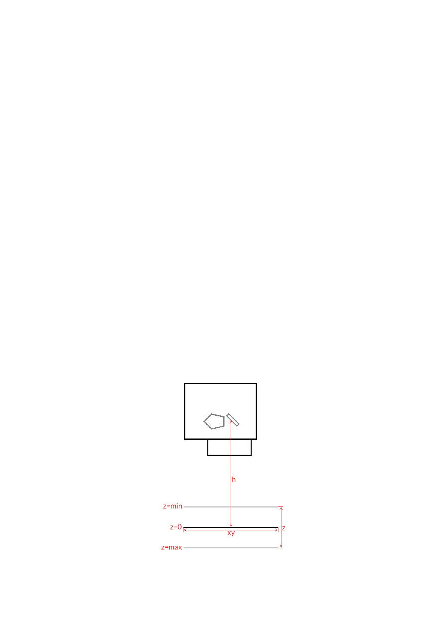
slantX
– trapezoidal correction along X-axis in range -45..45°
slantY
– trapezoidal correction along Y-axis in range -45..45°
Return:
E170X_OK
or an
E170X_ERROR_
-return code in case of an error
int E170X_set_z_correction2(const unsigned char n,const int flags,const double
gainZ,const int offsetZ,const unsigned int h,const double xy_to_z_ratio)
Set additional Z correction parameters.
This function may be used to adjust the Z-axis and in cases where third axis is used with a large Z working range
for an additional Z-focus-correction. Here additional deviation occurs when no F-Theta lens is used caused by
the fact that the beam is always sent from the centre of the scanhead – which causes some kind of projection
resulting in larger or smaller X and Y positions depending on the real Z height. This deviation can be adjusted by
an internal Z-focus-correction.
Beside of that, the Z-position can be adjusted via a gain factor and by using an offset, shifting it into a specific
direction
This is a stream-command, means its parameters are applied at a point in stream that is relative to the other
stream commands and changed values apply only to these vector data and coordinates, which are sent after
calling this function.
This function requires firmware version 27 or newer.
Parameters:
n
– the 1-based board instance number as returned by
E1803_set_connection()
flags
– optionally set the flag
E1803_COMMAND_FLAG_ZCORR_MIRRORZ
to invert the orientation of the Z-
axis, for normal scanhead working in correct direction, this value can be left at 0
gainZ
– scales the Z axis by the given factor, when set to 1.0, no scaling is applied to the Z-coordinates
offsetZ
– shifts the Z-position into the given direction (using unit bits), when set to 0, no offset is applied to
the Z-coordinates
h
– the vertical height from last mirror of the scanhead to the working area (Z-position 0 of working area) in
unit bits, when set to 0, the Z-focus-correction is disabled
xy_to_z_ratio
– factor specifying the ratio between maximal horizontal working area size and maximal
vertical movement size. As an example: when the working area has a size of 100 x 100 mm and the Z-axis has a
maximum movement range of -20 mm .. 20 mm, the ratio to be set is 2,5 (100 mm horizontal divided by 40 mm
vertical); when this value is set to a ratio equal or smaller than 0.0, the Z-focus-correction is disabled
For more details about the Z-focus correction applied by setting the parameters
h
and
xy_to_z_ratio
,
please refer to the image below:
76

Here “h” is the height from the position where the beam hits the last mirror to the position of the working area
at z=0 position (in unit bits). “xy” is the width of the working area to be used together with the “z” range from
“z=min” to “z=max” to calculate the
xy_to_z_ratio
. All working area parameters like its width “xy” and the
“z”-range are expected to be the theoretical maximum of the full range, not the – possibly smaller – range used
in a specific setup.
Return:
E170X_OK
or an
E170X_ERROR_
-return code in case of an error
int E170X_set_speeds(unsigned char n, double jumpspeed,double markspeed)
Set scanner speed values to be used for all following vector data and until not replaced by other speed
values.
This is a stream-command, means its parameters are applied at a point in stream that is relative to the other
stream commands and changed values apply only to these vector data and coordinates, which are sent after
calling this function.
Parameters:
n
– the 1-based board instance number as returned by
E170X_set_connection()
jumpspeed
– scanner movement speed during jumps (movements when laser is off) in unit bits/msec and
range 1..4294960000
markspeed
– scanner speed during mark (movements when laser is on) in unit bits/msec and range
1..4294960000
Return:
E170X_OK
or an
E170X_ERROR_
-return code in case of an error
int E170X_set_overspeed(const unsigned char n,const unsigned int flags,const
double scannerLag,const double jumpFactor,const double reserved);
Turns on the overspeed function of the controller card which tries to move the scanhead with a
multiple of its nominal speed without damaging the marking result by massive distortions. This function call can
be used to enable and configure or to disable the overspeed-feature. Depending on the type of marking data
this function can save nameable amounts of marking time. It can be used with any kind of scanhead which meet
the following requirements:
•
hardware is a galvo-driven scanhead
•
is does not contain an internal speed limit that suppresses all speeds beyond an artificial limit
From technical point of view as soon as the overspeed function is enabled, all vector data are analysed by the
controller card. When vectors are found which are suitable to be driven with overspeed, specific acceleration
and deceleration ramps are done with these vectors to ensure the marking result itself is not distorted. Next
these vectors are driven with a multiple of its normal speed. Vectors which are not suitable to be used with the
overspeed function are left untouched, there neither any speed ramping is done nor is the nominal speed
changed.
This function requires firmware version 41 or newer.
Parameters:
n
– the 1-based board instance number as returned by
E170X_set_connection()
flags
– a set of operational flags that specify how the function has to be used, currently only
E170X_COMMAND_FLAG_STREAM
is allowed
scannerLag
– the lag (“tracking error”) of the scanner in unit msec; this value is predefined by the hardware of
the scanhead and should be available from its technical data; when this value is equal or less than 0.0, the
overspeed-function is turned off
jumpFactor
– the factor the nominal jump speed (as set via function
E170X_set_speeds()
) is allowed to
be exceeded during overspeed-drives; when this value is equal or less than 1.0, the overspeed-function is
turned off
reserved
– reserved for future use, has to be set to 0
Return:
E170X_OK
or an
E170X_ERROR_
-return code in case of an error
77
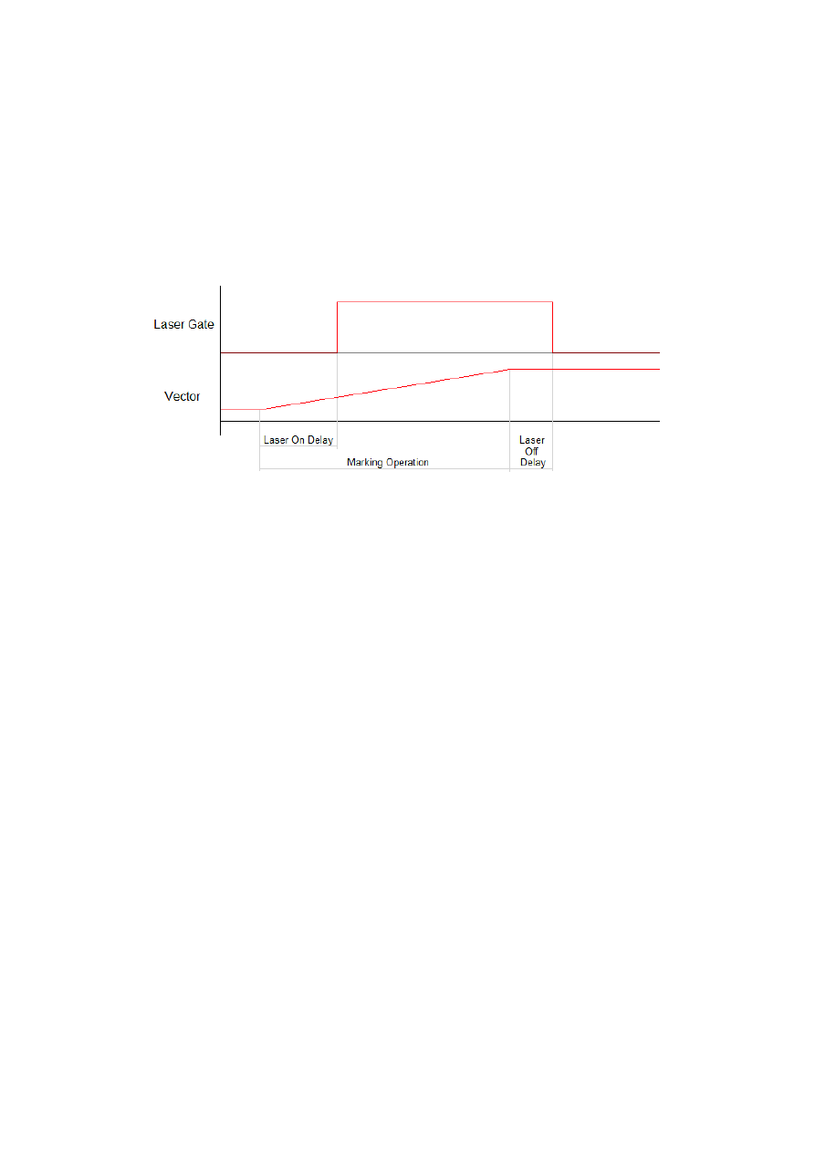
int E170X_set_laser_delays(const unsigned char n,double ondelay,double offdelay)
Set laser delay values to be used for all following vector data and until not replaced by other delay
values.
This is a stream-command, means its parameters are applied at a point in stream that is relative to the other
stream commands and changed values apply only to these vector data and coordinates, which are sent after
calling this function.
Parameters:
n
– the 1-based board instance number as returned by
E170X_set_connection()
ondelay
– laser on delay in unit microseconds, can be a negative or a positive value
offdelay
– laser off delay in unit microseconds, must be a positive value
Return:
E170X_OK
or an
E170X_ERROR_
-return code in case of an error
int E170X_set_scanner_delays(const unsigned char n,const unsigned int
flags,const double jumpdelay,const double markdelay,const double polydelay)
Set scanner delays in unit microseconds. Smallest possible value and resolution is 0.5 microseconds.
This is a stream-command, means its parameters are applied at a point in stream that is relative to the other
stream commands. So values set here apply only to these vector data that are sent after this command.
Parameters:
n
– the 1-based board instance number as returned by
E170X_set_connection()
flags
– here some flags can be set which add some further functional specifications and features to this
function. At the moment following flags are supported and can be OR-concatenated with each other:
•
E170X_COMMAND_FLAG_SCANNER_VAR_POLYDELAY
– when this flag is set, the value set via
polydelay
is not applied statically to every point within a polygon, but it is set dynamically depending
on the angle between two lines; no angle (a straight line) results in no delay while a 180 degree angle
results in a full delay as set by value
polydelay
; this flag requires firmware version 31 or newer
jumpdelay
– the jump delay value in unit microseconds
markdelay
– the mark delay value in unit microseconds
polydelay
– the in-polygon delay value in unit microseconds
Return:
E170X_OK
or an
E170X_ERROR_
-return code in case of an error
int E170X_set_laser_mode(unsigned char n, unsigned int mode)
Sets the laser mode to be used for all following operations, this value influences the signals emitted at
the connectors of the card. This function has to be called prior to setting any other laser parameters (like
frequency, standby-frequency, power).
This is a stream-command, means its parameters are applied at a point in stream that is relative to the other
stream commands.
78
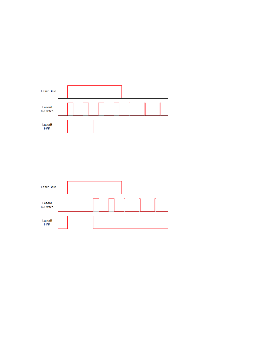
Parameters:
n
– the 1-based board instance number as returned by
E170X_set_connection()
mode
- the laser mode, here one of the following values is possible:
•
E170X_LASERMODE_CO2
– for controlling CO2 lasers, this mode supports stand-by frequency at
LaserA output (to be set with function
E170X_set_standby()
) and PWM-modulated frequencies
during marking and for power control (to be set with function
E170X_set_laser_timing()
)
•
E170X_LASERMODE_YAG1
– for controlling YAG lasers, this mode supports stand-by and Q-Switch
frequency at LaserA output (to be set with function
E170X_set_standby()
) and a first pulse killer
signal at output LaserB that is issued on beginning of a mark together with the Q-Switch frequency (to
be set with function
E170X_set_fpk()
):
Here Q-Switch signal is started together with laser gate and FPK pulse. At end of mark when laser gate
is turned off stand-by frequency is emitted at LaserA.
•
E170X_LASERMODE_YAG2
- for controlling YAG lasers, this mode supports stand-by and Q-Switch
frequency at LaserA output (to be set with function
E170X_set_standby()
) and a first pulse killer
signal at output LaserB that is issued on beginning followed by Q-Switch frequency that starts when
FPK pulse has finished:
Here FPK and laser gate are started together. Q-Switch signal is started at end of FPK pulse. At end of
mark when laser gate is turned off, stand-by frequency and pulse-width is emitted at LaserA instead of
Q-Switch frequency.
•
E170X_LASERMODE_YAG3
– for controlling YAG lasers, this mode supports stand-by and Q-Switch
frequency at LaserA output (to be set with function
E170X_set_standby()
) and a first pulse killer
signal at output LaserB that is issued on beginning followed by Q-Switch frequency that starts after a
freely configurable time period “yag3QTime”:
79
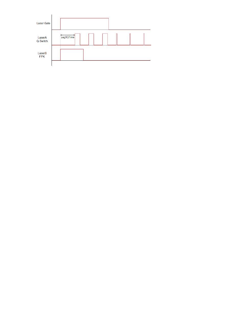
Here FPK and laser gate are started together. Q-Switch signal is started after yag3QTime has elapsed
according to the beginning of FPK pulse. This time value can be set using function
E170X_set_fpk()
.
At end of mark when laser gate is turned off, stand-by frequency and pulse-width is emitted at LaserA
instead of Q-Switch frequency.
•
E170X_LASERMODE_CRF
– for controlling lasers that require a continuously running frequency (like
fiber-lasers), this frequency is emitted at LaserA output and can be set and changed by calling function
E170X_set_standby()
.
•
E170X_LASERMODE_DFREQ
– for controlling special lasers that require two frequencies, the second,
continuously running frequency is emitted at LaserB output and can be set with function
E170X_set_laserb()
•
E170X_LASERMODE_MOPA
– for fiber lasers which are driven by a main oscillator and power amplifier
and that are power-controlled via LP8 digital port and latch bit
Return:
E170X_OK
or an
E170X_ERROR_
-return code in case of an error
int E170X_set_laser(const unsigned char n,const unsigned int flags,const char
on)
Switches the laser on or off independent fro many mark or jump commands.
Parameters:
n
– the 1-based board instance number as returned by
E170X_set_connection()
flags
– handling flags specifying the behaviour of this command,
E170X_COMMAND_FLAG_STREAM
to use it
as stream command,
E170X_COMMAND_FLAG_DIRECT
to execute it immediately and independent on current
stream and execution state; in case
E170X_COMMAND_FLAG_STREAM
is used, please ensure this function call is
followed by other stream commands, elsewhere the laser is turned off for security reasons as soon as no more
data are available to process in order to not to let the laser fire while the card is waiting
on
– set to 1 to turn the laser on or to 0 to turn it off
Return:
E170X_OK
or an
E170X_ERROR_
-return code in case of an error
int E170X_set_wobble(const unsigned char n,unsigned int x,unsigned int y,double
freq)
This function gives the possibility to not to let the laser beam follow the given path directly but to
rotate around the specified path and lasers current position. Depending on chosen wobble-parameters and
marking speed, this results either in a thick or a sinusoidal line. This call sets wobble parameters to be used for
all following vector data and until not replaced by other wobble values or by 0 which disables wobble mode.
This is a stream-command, means its parameters are applied at a point in stream that is relative to the other
stream commands.
Parameters:
n
– the 1-based board instance number as returned by
E170X_set_connection()
x
– wobble amplitude in x direction in units bits and range 1..10000000
y
– wobble amplitude in y direction in units bits and range 1..10000000
freq – wobble frequency in Hz in range 1..25000
80
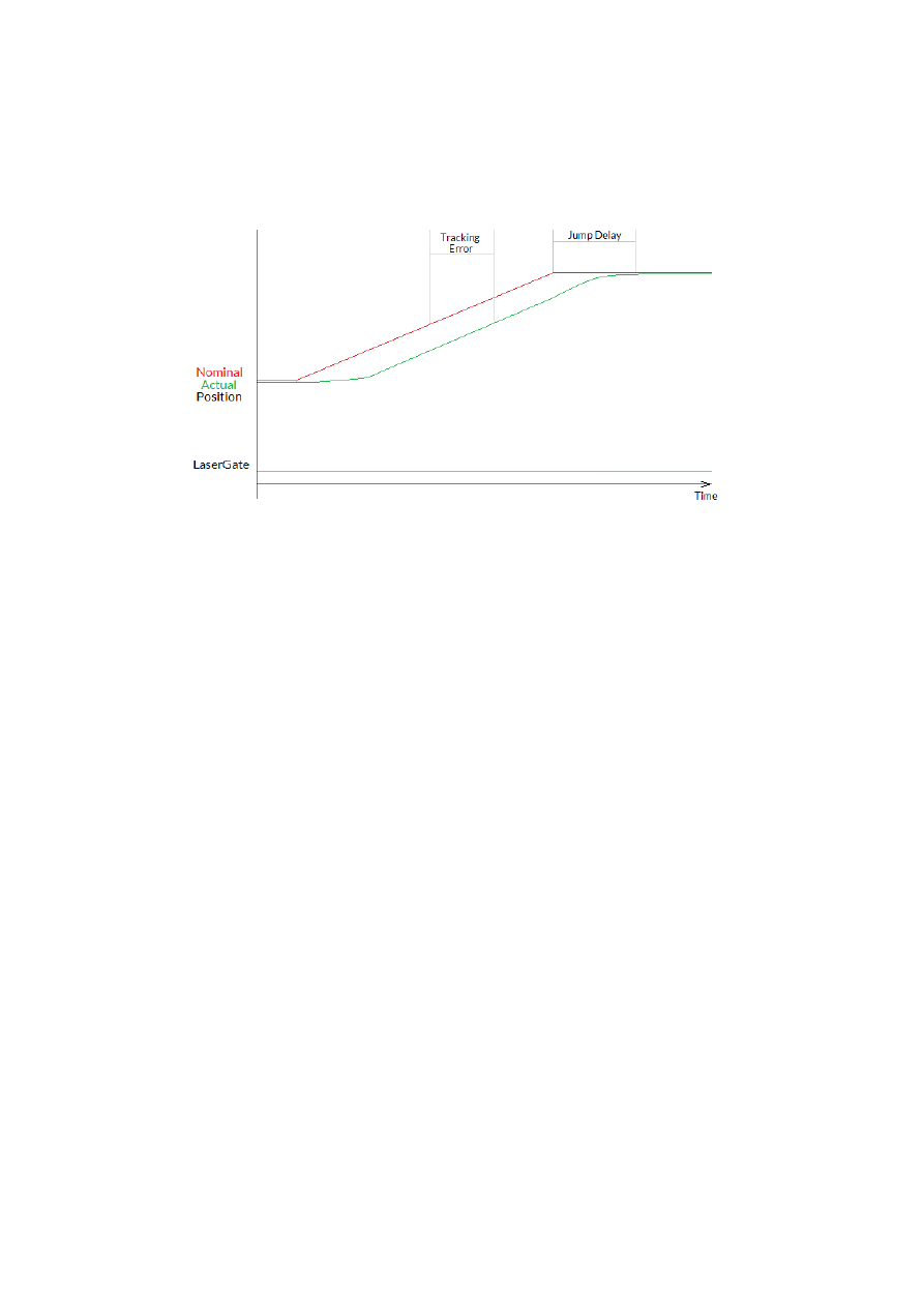
Return:
E170X_OK
or an
E170X_ERROR_
-return code in case of an error
int E170X_jump_abs(const unsigned char n,int x,int y,int z)
Perform a jump (movement with laser turned off) to the given position. This causes a galvo movement
from current position to the one specified by this functions parameters using the jump speed and taking the
jump delay into account:
When laser was turned on before this function is called, laser is turned off at the beginning with a delay
specified by laser off delay (please refer to description of
E170X_mark_abs()
for a diagram showing laser off
delay too).
This is a stream-command, means it is executed at a point in stream that is relative to the other stream
commands.
Parameters:
n
– the 1-based board instance number as returned by
E170X_set_connection()
x
– the x-coordinate in unit bits the scanner has to jump to
y
– the y-coordinate in unit bits the scanner has to jump to
z
– the z-coordinate in unit bits the scanner has to jump to (requires a hardware that is equipped with Z-
channel)
Return:
E170X_OK
or an
E170X_ERROR_
-return code in case of an error
int E170X_mark_abs(const unsigned char n,int x,int y,int z)
Perform a mark (movement with laser turned on) to the given position. This causes a galvo movement
from current position to the one specified by this functions parameters using the mark speed and taking the
mark delay into account. When laser was turned off before this function is called, laser is turned on at the
beginning with a delay specified by laser on delay:
81
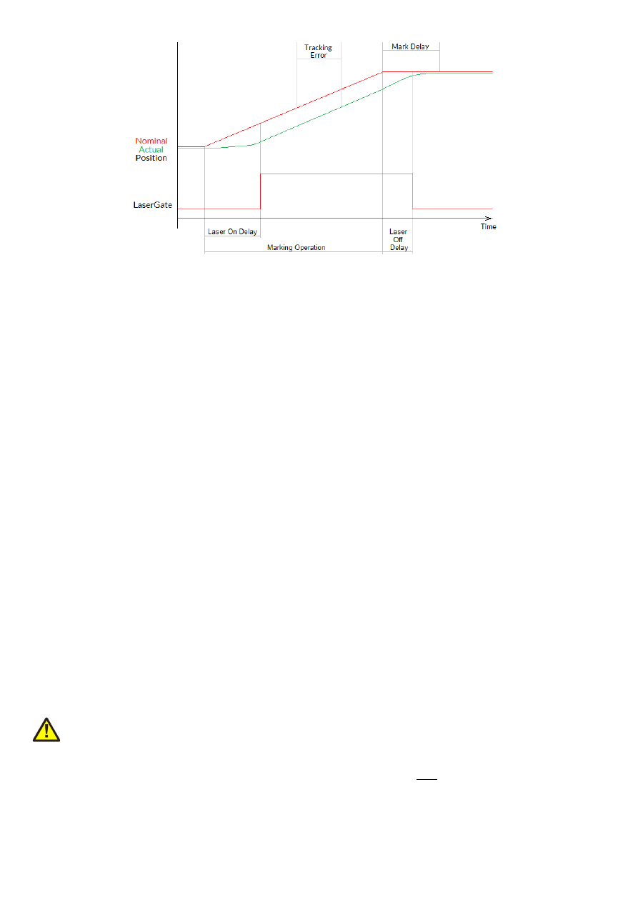
This is a stream-command, means it is executed at a point in stream that is relative to the other stream
commands.
Parameters:
n
– the 1-based board instance number as returned by
E170X_set_connection()
x
– the x-coordinate in unit bits the scanner has to move to
y
– the y-coordinate in unit bits the scanner has to move to
z
– the z-coordinate in unit bits the scanner has to move to (requires a hardware that is equipped with Z-
channel)
Return:
E170X_OK
or an
E170X_ERROR_
-return code in case of an error
int E170X_get_pos(const unsigned char n,int *x,int *y,int *z)
This function returns the last position of the scanner:
•
when an XY3-100 scanhead is connected, that provides its actual position, these values are returned
•
when no such scanhead is connected, the last nominal position sent to the head are returned
The function needs the controller to be in idle-mode, means no marking operation is allowed to run in order to
get the position information.
Please note: when a correction file is set, and/or a matrix is set and/or an offset is set and/or any other function
is used which modifies the position data, the coordinates returned here are
not
the values which have been sent
with the last call to
E170X_jump_abs()
or
E170X_mark_abs()
or
E170X_set_pos()
as they have been
processed and modified by these correction functions. So while the jump/mark functions set position data
according to the desired coordinate system, the values returned by
E170X_get_abs()
are the real-world
coordinates at the hardware.
This function requires firmware version 42 or newer.
Return:
E170X_OK
or an
E170X_ERROR_
-return code in case of an error
int E170X_set_pos(const unsigned char n,int x,int y,int z,unsigned char laserOn)
Perform a raw, immediate movement to the given position.
HANDLE WITH CARE! This function causes galvo movement to the given position immediately, without
respect to any mark or jump speed values, without micro-vectorisation or intermediate steps! This means it can
result in a very heavy movement for the galvos and in worst case it may cause some damage! Since the resulting
movement speed may be way too high for the used galvos, they may overshoot and need some time until the
desired position is reached. So this function is mainly intended to be used for very small position changes in
respect to the galvos current position.
82

This is a stream-command, means it is executed at a point in stream that is relative to the other stream
commands.
Parameters:
n
– the 1-based board instance number as returned by
E170X_set_connection()
x
– the x-coordinate in unit bits the scanner has to jump to
y
– the y-coordinate in unit bits the scanner has to jump to
z
– the z-coordinate in unit bits the scanner has to jump to (requires a hardware that is equipped with Z-
channel)
laserOn
– specifies if the movement has to be done with laser turned on (1) or off (0)
Return:
E170X_OK
or an
E170X_ERROR_
-return code in case of an error
int E170X_set_pixelmode(const unsigned char n,const unsigned int mode,const
double powerThres,const unsigned int res)
Set the operational mode for
E170X_mark_pixelline()
. This function influences the behaviour
when marking a pixel line. This is a stream-command, means its parameters are applied at a point in stream that
is relative to the other stream commands.
This function requires firmware version 19 or newer.
Parameters:
n
– the 1-based board instance number as returned by
E170X_set_connection()
mode
– pixel marking mode, this parameter can be set to:
•
0 – default mode, while marking a pixel line the controller tries to perform jumps when power
is below of the given threshold
powerThres
to save marking time
•
E170X_PIXELMODE_NO_JUMPS
– no jumps are performed, the given power threshold is
ignored and the full pixel line is done with marking speed; this mode is slower but can result in
more accurate and more exact images
•
E170X_PIXELMODE_JUMP_N_SHOOT
– marking of the line is no longer done with a
continuous movement but with a sequence “jump to position shoot jump to next position
→
→
shoot jump to next position shoot...”; here the shoot-time is equal to the laser-off-delay
→
→
→
minus laser-on-delay as set with function
E170X_set_laser_delays()
•
E170X_PIXELMODE_HW_POWER_CONTROL
– when this flag is set, the controller card takes
care about setting the power for the pixels. This works only when a lasermode is chosen where
the scanner card supports native power control. When this flag is set, a power-callback,
handed over together with a call to
E170X_mark_pixelline()
is ignored.
•
E170X_PIXELMODE_GATE_POWER_CONTROL
– this is a special bitmap marking mode where
no real power control is supported. When this flag is set, the LaserGate output is toggled
depending on the required output power. Since this output supports only states LOW and
HIGH, this bitmap marking mode results in black and white images only
•
E170X_PIXELMODE_JUMP_LEAVE_POWER
– during bitmap marking, when no flag
E170X_PIXELMODE_NO_JUMPS
is set, below of a specific power threshold a jump is
performed. By default, prior to such a jump, the laser power is set to 0 to handle faultily lasers
that have spurious emissions even when LaserGate is at LOW. For laser types, which do not
suffer from such emissions, this flag can be set. It leaves the last power value active also during
jumps, which saves some marking time. So this flag can be used for speed-optimising bitmap-
marking.
powerThres
– this value is used only in default mode, when the marking power for some pixels is below of the
given value (in unit percent), a jump is performed to save marking time, during this jump the laser is off and no
marking is done
res
– reserved, set always to 0
Return:
E170X_OK
or an
E170X_ERROR_
-return code in case of an error
83

int E170X_mark_pixelline(const unsigned char n,int x,int y,int z,int
pixWidth,int pixHeight,int pixDepth,unsigned int pixNum,double
*pixels,E170X_power_callback power_callback,void *userData)
This function can be used to mark a single line of a bitmap image. Here horizontal, vertical and even 3D
bitmap lines (going into depth) can be marked. Direction and orientation of the line to be marked can be chosen
freely. A full image can be created by concatenating several lines. Power control during marking of such a
bitmap line is not limited to some specific power outputs, it can be fully customised via a callback function.
Parameters:
n
– the 1-based board instance number as returned by E170X_set_connection()
x, y, z
– the starting coordinates of the line in unit bits
pixWidth
– the width of a single pixel (in unit bits), when this is set to a value greater or smaller than 0 while all
the others are equal 0, a horizontal line is drawn; the sign of the value specifies the marking direction
pixHeight
– the height of a single pixel (in unit bits), when this is set to a value greater or smaller than 0 while
all the others are equal 0, a vertical line is drawn; the sign of the value specifies the marking direction
pixDepth
– the depth of a single pixel (in unit bits, requires a 3D-capable scanhead), when this is set to a value
greater or smaller than 0 while all the others are equal 0, line goes into depth; the sign of the value specifies the
marking direction
pixNum
– the number of pixel data contained in the array of intensity values handed over with the following
parameter
pixels
– an array of double-values with a length equal the number of pixels specified with
pixNum
and with
an allowed range of 0.0..100.0 specifying the intensity; every entry of this array is equal to one pixel of the
bitmap, so a greyscale-pixelline with brightness values in range 0..255 has to be converted to values in range
0.0..100.0
power_callback
– this is a callback function of type
int (*E170X_power_callback)(unsigned char n, double power, void *userData)
which is used to set the power for every pixel. There these
E170X_
-functions have to be called that belong to
the used laser type and set the power values according to it's hardware capabilities. Within the power callback
function only stream commands are allowed to be called. It is not possible to use external devices that are not
synchronous to E1701 command stream. The power callback has to return with
E170X_OK
when setting of
power was successful. In case of an error the appropriate error code has to be returned, the pixel marking
function will be cancelled in such a case too and does not finish marking of the line. Parameter
n
is the 1-based
board instance number specifying the board the power has to be changed for, power is the power to be set in
unit percent and
userData
are some free to use, custom data that can be handed over on call to
E170X_mark_pixelline()
.
userData
- here some custom data can be handed over which are forwarded on and handed over at every call
of the power-callback
Return:
E170X_OK
or an
E170X_ERROR_
-return code in case of an error
int E170X_set_matrix(const unsigned char n,const unsigned int flags,const double
m11,const double m12,const double m21,const double m22)
Specify a 2x2 matrix that contains scaling and rotation corrections for the output. When a given matrix
element parameter has a value smaller or equal -10000000 it is ignored and the previous/default value is kept
at this position in matrix. With this command any correction set with
E170X_set_xy_correction2()
will
be overwritten.
This is a stream-command, means its parameters are applied at a point in stream that is relative to the other
stream commands.
Parameters:
n
– the 1-based board instance number as returned by
E170X_set_connection()
flags
– reserved for future use, set to 0 for compatibility
m11
– first matrix element in first row
m12
– second matrix element in first row
84

m21
– first matrix element in second row
m22
– second matrix element in second row
Return:
E170X_OK
or an
E170X_ERROR_
-return code in case of an error
int E170X_set_trigger_point(const unsigned char n)
Specifies a point in data stream where execution has to stop until an external trigger signal (mark start)
or a manual release of this trigger point is detected. This expects a rising edge on ExtStart input or calling of
function
E170X_release_trigger_point()
.
This is a stream-command, means it is executed at a point in stream that is relative to the other stream
commands.
Parameters:
n
– the 1-based board instance number as returned by
E170X_set_connection()
Return:
E170X_OK
or an
E170X_ERROR_
-return code in case of an error
int E170X_release_trigger_point(const unsigned char n)
This function should be called only when a call to
E170X_set_trigger_point()
was done before.
It acts like an external trigger signal, releases the waiting condition and lets the controller start processing. So
this function provides some kind of software-simulated external start-signal.
ATTENTION: this command will not arrive at the controller when there is no more space left on it, means when
all controller-internal buffers are filled. So after a call to
E170X_set_trigger_point()
and during sending
of commands and data to the controller, application has to ensure there is some space left in controller's
buffers. This can be done by calling
E170X_get_free_space()
with flag
E170X_FREE_SPACE_PRIMARY
for checking the available space in primary buffer. It is recommended to leave space for at least 10000 elements
in primary buffer in order to let a call to
E170X_release_trigger_point()
work properly.
When the buffers already have been filled completely, this function will no longer work and marking can be
started only by applying the ExtStart hardware signal.
This is not a stream-command, it is applied to controller immediately.
Parameters:
n
– the 1-based board instance number as returned by
E170X_set_connection()
Return:
E170X_OK
or an
E170X_ERROR_
-return code in case of an error
int E170X_set_signal_point(const unsigned char n,const unsigned int flags)
Specifies a point in data stream where execution has to stop until an external signal (mark start) is
detected. Different to
E170X_set_trigger_point()
this function does not expect a rising edge but a
specific signal at the ExtStart input. The signal and the functions behaviour can be specified with the parameter
flags
which can consist of the following, OR-concatenated flags:
E170X_COMMAND_FLAG_HIGH_LEVEL
– when this flag is set, the function waits for a HIGH-leven alt the
ExtStart input, when it is not set, it waits for a LOW-signal
E170X_COMMAND_FLAG_SILENT
– by default, every time the function waits for a specific level, causes a state-
change by setting the state-flag
E170X_CSTATE_WAIT_EXTSIGNAL
and by resetting it as soon as the
required signal was detected. According to the workign principle of the controllers states, each of these state
changes has to be fetched by a corresponding call to
E170X_get_card_state()
. Now when this function to
wait for a signal is used very often, this can cause a load of state-changes being enqueued which can’t be
fetched by the calling application fast enough. In this situation (or whenever the waiting-state of the controller
is not interesting to be known), the flag
E170X_COMMAND_FLAG_SILENT
can be set. Then the function
operates silently without any feedback via the controllers state.
This is a stream-command, means it is executed at a point in stream that is relative to the other stream
commands.
85

Parameters:
n
– the 1-based board instance number as returned by
E170X_set_connection()
value
– the signal level to wait for at ExtStart input, here 0 or 1 can be specified
Return:
E170X_OK
or an
E170X_ERROR_
-return code in case of an error
int E170X_set_sync(const unsigned char n,const unsigned int flags,const unsigned
int value)
This function sends a synchronisation
value
to the controller. As soon as marking reaches the related
position in stream, the value returned by function
E170X_get_sync()
changes to the value given here.
This command delays execution of the data by 0,5 usec, so it should not be used excessively. A value of
0xFFFFFFFF disables this function.
This function requires firmware version 30 or newer.
Parameters:
n
– the 1-based board instance number as returned by
E170X_set_connection()
flags
– currently unused, set to 0 for future compatibility
value
– the value to be used as sync-identifier, here on every call a different value should be handed over in
order to differentiate what is returned by
E170X_get_sync()
.
Return:
E170X_OK
or an
E170X_ERROR_
-return code in case of an error
unsigned int E170X_get_sync(const unsigned char n)
Returns a sync-identifier as set by
E170X_set_sync()
as soon as the related position in stream was
reached.
This function requires firmware version 30 or newer.
Parameters:
n
– the 1-based board instance number as returned by
E170X_set_connection()
Return: the last sync-identifier which was identified and processed in stream of commands or 0xFFFFFFFF
when function is not used/turned off
int E170X_execute(const unsigned char n)
Starts execution of all previously sent commands in case card is not already outputting these data. The
E1701 Easy Programming Interface does not use the concept of two or more lists that have to be handled and
switched by the calling application. Nevertheless the user has to ensure the card can start marking by calling
this function after all vector data have been sent to the card. Here it does not matter if the card is already
executing or not, subsequent calls to
E170X_execute()
do not influence marking behaviour. More than this:
in case very much data are sent to the card, it starts marking automatically after a defined fill level was reached.
Due to this automated, fill level dependent start it would not be necessary to call
E170X_execute()
. But in
situations where only very few data are sent to the card, it is necessary to call this function in order to start
marking also in these cases where the internal fill threshold is not reached and where the card would not start
marking immediately. Thus it is recommended to always call this function after all marking data have been sent.
Marking is finished only when STOP (ExtStop signal input or
E170X_stop_execution()
)is invoked or when
the internal buffer is empty. When internal buffer runs empty because subsequent data are not sent fast
enough, an additional call to
E170X_execute()
is necessary in order to output the remaining data.
This is not a stream command since it controls the already sent stream of commands.
Parameters:
n
– the 1-based board instance number as returned by
E170X_set_connection()
86

Return:
E170X_OK
or an
E170X_ERROR_
-return code in case of an error
int E170X_stop_execution(const unsigned char n)
Stops the currently running execution as fast as possible and drops all marking data that still may be
queued. Calling this function also would drop all laser and scanner parameters that are already sent but not yet
processed. Thus after calling this function it may be necessary to set scanner and laser parameters again in
order to ensure they are used for following operations.
This is not a stream command since it controls the current stream of commands.
PLEASE NOTE:
this function should not be called on the off-chance “to be sure nothing is running”. The
command works asynchronously and causes a state-change which can have some unwanted side-effects when
it is used without a specific reason. So calling the function should be done only when the controller is really in
state marking/running, and after calling it, no other functions have to be used until the state
(
E170X_get_card_state()
) has changed back to idle. As the stop is done as fast as possible, the point, at
what the stream is stopped, is undefined. Means any function that has been called between the last call to
E170X_execute()
and
E170X_stop_execution()
may not have an effect and probably needs to be
repeated.
Parameters:
n
– the 1-based board instance number as returned by
E170X_set_connection()
Return:
E170X_OK
or an
E170X_ERROR_
-return code in case of an error
int E170X_halt_execution(const unsigned char n,const unsigned char halt)
Halts or continues the processing and output of marking data. On
halt=1
marking is stopped next
time the laser is off. Different to a full stop no vector data are flushed. On continue (
halt=0
) controller
continues processing at the point where halt occurred. When marking is stopped with
E170X_stop_execution()
the halt-condition is cleared too, means on next transmission of new marking
data they are processed without the need to explicitly continue last operation. This command requires
firmware version 16 or newer.
Parameters:
n
– the 1-based board instance number as returned by
E170X_set_connection()
halt
– 1 to halt operation next time the laser is off, 0 to continue a previously halted operation
Return:
E170X_OK
or an
E170X_ERROR_
-return code in case of an error
unsigned int E170X_get_startstop_state(const unsigned char n)
This function returns a bit pattern that informs about state of the start and stop input pins.
This is not a stream command since it returns the current state immediately. Here “current state” means the last
known state. When the state changes during this call, it may be possible the previous, no longer actual state is
given back since transmission of data from controller to host is done asynchronously and independent from a
call to this function.
Parameters:
n
– the 1-based board instance number as returned by
E170X_set_connection()
Return: a bit pattern specifying the current state:
•
bit 0 and 1 (0x00000003) specify if the start input was set after last call of this function, when these
bits are set, a rising edge has been detected at this input; calling this function resets the internal state
of these bits, means when it is called again and when no new rising edge has been detected meanwhile,
these bits will be 0
•
bit 2 and 3 (0x0000000C) specify if the stop input was set after last call of this function, when they are
set, a rising edge has been detected at this input; calling this function resets the internal state of these
87

bits, means when it is called again and when no new rising edge has been detected at top input
meanwhile, these bits will be low
•
bit 12 (0x00001000) this bit signals the start input is low, as long as this bit is set no start input signal is
detected
int E170X_get_card_state(const unsigned char n,unsigned int *value)
This function returns a bit pattern that informs about cards current operational state. Here “current
state” means the last known state. When the state changes during this call, it may be possible the previous, no
longer actual state is given back since transmission of data from controller to host is done asynchronously and
independent from a call to this function.
The card-states are enqueued internally in order to not to lose a “busy”-state which may be available for a very
short time only in case of very small and fast marking cycles. So every state change caused by the calling
application results in on state change returned by this function. This means for every marking cycle the
application has to wait for two state changes: first wait until this function signals “busy”
(
E170X_CSTATE_PROCESSING
|
E170X_CSTATE_MARKING
) next wait until this function signals “ready” (0).
During transfer of vector data and scanner/laser parameters this function should be called as rarely as possible:
every call of
E170X_get_card_state()
performs a full cycle of transmission and receiving of data to and
from the controller. Dependent on the current transmission state this may result in submission of a small block
of data which does not uses the full available bandwidth. On excessive use of this function this can slow down
the whole transfer of data.
This is not a stream command since it returns the current state immediately.
Parameters:
n
– the 1-based board instance number as returned by
E170X_set_connection()
state
– pointer to a variable where the card state has to be written to: a bit pattern of or-concatenated
constants specifying the current state:
•
E170X_CSTATE_MARKING
– card is currently marking
•
E170X_CSTATE_PROCESSING
– card has received some data that are enqueued for marking
•
E170X_CSTATE_WAS_START_PRESSED
– the ExtStart input was triggered, this flag is cleared after it
has bean read and is set again only when ExtStart was triggered again
•
E170X_CSTATE_WAS_STOP_PRESSED
– the ExtStop input was triggered, this flag is cleared after it
has bean read and is set again only when ExtStop was triggered again
•
E170X_CSTATE_FILE_WRITE_ERROR
– this flag is returned only in case stand-alone data are written
to the microSD card and in case an file error occurs during this procedure. As writing an EPR file is done
as asynchronous stream, errors during this procedure are not announced by the functions which are
called but only by this error state. For more information about writing of stand alone data please refer
to section “9.1.1 Writing of stand-alone data”
•
E170X_CSTATE_WAIT_EXTTRIGGER
– the controller is in state “marking” but is not yet processing
any data as it is waiting for an external trigger
•
E170X_CSTATE_HALTED
– the controller is in state “marking” but is not yet processing any data as it is
currently halted by function
E170X_halt_execution()
•
E170X_CSTATE_WAIT_INPUT
– the controller is in state “marking” but is not yet processing any data
as it is waiting for a specific input pattern at the digital inputs
•
E170X_CSTATE_SAC_READY
– this flag applies only to stand-alone modes; it is similar to output
DOut0 and signals the controller has loaded a stand-alone file and is ready for marking
•
E170X_CSTATE_SAC_MARKING
– this flag applies only to stand-alone modes; it is similar to output
DOut1 and signals the controller is marking a loaded EPR file
•
E170X_CSTATE_SAC_CTLXY
– this flag applies only to stand-alone modes; it signals a “
ctlxy
”
command was received and the related mode is active
When the function returns an error code instead of E170X_OK, this value is undefined and can't be used.
Return:
E170X_OK
or an
E170X_ERROR_
-return code in case of an error
int E170X_delay(const unsigned char n, double delay)
88

Pause marking for the given time.
This is a stream-command, means it is executed at a point in stream that is relative to the other stream
commands.
Parameters:
n
– the 1-based board instance number as returned by
E170X_set_connection()
delay
- time to wait until marking continues in unit usec, smallest possible value is 0,500 usecs
Return:
E170X_OK
or an
E170X_ERROR_
-return code in case of an error
int E170X_set_laser_timing(unsigned char n, double frequency, double pulse)
Set the frequency and pulse-width to be used during marking at LaserA output of LP8 Extension Board
or Digital XY2-100 Baseboard.
This is a stream-command, means its parameters are applied at a point in stream that is relative to the other
stream commands.
Parameters:
n
– the 1-based board instance number as returned by
E170X_set_connection()
frequency
– emitted frequency in unit Hz and in range 25..20000000 Hz
pulse
– pulse width in usec, this value has to be smaller than period length that results out of frequency
Return:
E170X_OK
or an
E170X_ERROR_
-return code in case of an error
int E170X_set_standby(const unsigned char n,const double frequency,const double
pulse, const bool force)
Set the frequency and pulse-width to be used during jumps, as stand-by frequency or as continuously
running frequency at LaserA output of LP8 Extension Board or Digital XY2-100 Baseboard.
This is a stream-command, means its parameters are applied at a point in stream that is relative to the other
stream commands.
Parameters:
n
– the 1-based board instance number as returned by
E170X_set_connection()
frequency
– emitted frequency in unit Hz and in range 25..20000000 Hz. When a value of 0 is given, the
frequency at LaserA output is turned off at end of mark.
pulse
– pulse width in usec, this value has to be smaller than period length that results out of
frequency
force
– when set to true, the new stand-by frequency is not applied the next time the laser is turned off, but
immediately
Return:
E170X_OK
or an
E170X_ERROR_
-return code in case of an error
int E170X_set_laserb(const unsigned char n,const double frequency,const double
pulse)
Set the frequency and pulse-width to be used at LaserB output of LP8 Extension Board or Digital XY2-
100 Baseboard. To use LaserB as second frequency output, a laser mode with flag
E170X_LASERMODE_DFREQ
has to be configured.
This is a stream-command, means its parameters are applied at a point in stream that is relative to the other
stream commands.
This function requires firmware version 19 or newer.
Parameters:
n
– the 1-based board instance number as returned by
E170X_set_connection()
frequency
– emitted frequency in unit Hz and in range 25..20000000 Hz
pulse
– pulse width in usec, this value has to be smaller than period length that results out of frequency
Return:
E170X_OK
or an
E170X_ERROR_
-return code in case of an error
89

int E170X_set_fpk(const unsigned char n, double fpk, double yag3QTime)
Set the parameters for first pulse killer signal that is emitted via LP8 Extension Board or Digital XY2-
100 Baseboard whenever the laser is turned on; this applies to YAG-modes only and is emitted as one single
pulse at LaserB output.
This is a stream-command, means its parameters are applied at a point in stream that is relative to the other
stream commands.
Parameters:
n
– the 1-based board instance number as returned by
E170X_set_connection()
fpk
– the length of the first pulse killer signal in usec
yag3QTime
– the length of the first pulse killer signal in usec, this value is used only when laser mode
E170X_LASERMODE_YAG3
is set, elsewhere it is ignored
Return:
E170X_OK
or an
E170X_ERROR_
-return code in case of an error
int E170X_get_free_space(const unsigned char n,int buffer)
This function returns the space (in unit "commands") that is free in one of the buffers of E1701. Here
parameter
buffer
decides which buffer has to be checked.
Parameters:
n
– the 1-based board instance number as returned by
E170X_set_connection()
buffer
– expects a constant which decides what buffer has to be checked, it has to be set to one of the
following values:
•
E170X_FREE_SPACE_PRIMARY
– return size of the primary buffer; it can be used to avoid memory on
host system is filled which may happen when vector data are sent to the controller while it's internal
buffers are already full. In this case these data would have been stored on host side consuming some
memory there. Using this function this problem can be avoided by sending commands only in case this
function returns a value that is (much) larger than 0.
The primary buffer that can be checked by using this value is one of two available buffers on E1701
controller. The primary one has a size of 900000 and is used to feed the secondary buffer (with a size of
17 million). So when this function returns 900000, this does not mean the buffer is empty and no
vector data currently processed – they still may be stored in secondary buffer. So to check the
operational state of the controller, only function
E170X_get_card_state()
can be used.
This buffer has also to be checked when function
E170X_release_trigger_point()
is used in
order to ensure the command can arrive at the controller. For a detailed description please refer to
explanation of
E170X_release_trigger_point()
above.
•
E170X_FREE_SPACE_SECONDARY
– return size of the secondary buffer; this one is filled by data from
primary buffer and contains raw commands (like single micro vectors that concatenate to a full vector
during output).
Return: -1 in case the function failed or the amount of free space in primary buffer.
void E170X_get_version(const unsigned char n, unsigned short *hwVersion,
unsigned short *fwVersion)
Get the hardware and software version of the used board. It is recommended to call this function after
successful connect always and check if used hardware and firmware version is at least a version that is known
to work with own software.
This is not a stream command, it is executed immediately and independent from all other commands.
Parameters:
n
– the 1-based board instance number as returned by
E170X_set_connection()
hwVersion
– pointer to a variable where the hardware revision/version number is written into
90

fwVersion
– pointer to a variable where the revision/version number of the firmware running on the board is
written into
const int E170X_get_library_version()
Returns an integer value which is an identifier specifying the version of this shared library. In decimal
notation this identifier uses format "Mmmrrr" where "M" is the major version, "m" the minor version number
and "r" the release count. The bigger the whole returned number is, the newer the library is.
int E170X_get_serial_number(const unsigned char n,char *serial,const int length)
Reads the serial number of the used board and returns it as 7 bit ASCII data.
This is not a stream command, it is executed immediately and independent from all other commands.
This function requires a firmware version 39 or newer.
Parameters:
n
– the 1-based board instance number as returned by
E170X_set_connection()
serial
– pointer to a char-array where the serial number has to be stored into, this memory area needs to
have a size of at least 40 bytes
length
– available length of the memory area where
serial
points to
Return:
E170X_OK
or an
E170X_ERROR_
-return code in case of an error
int E170X_lp8_write(const unsigned char n, unsigned int flags, unsigned char
value)
Sets the LP8_0..LP8_7 outputs of 8 bit laser port of LP8 Extension Board without touching the related
latch output. Total execution time of this command during processing on controller is 1 usec.
This function does not change the value at the analogue AOut0 output of LP8 Extension Board.
Depending on the value of parameter flags this is either a stream-command (means it is executed at a point in
stream that is relative to the other stream commands) or a direct command (means it is executed immediately
on calling). This command requires firmware version 16 or newer.
Parameters:
n
– the 1-based board instance number as returned by E170X_set_connection()
flags
– handling flags specifying the behaviour of this command,
E170X_COMMAND_FLAG_STREAM
to use it
as stream command,
E170X_COMMAND_FLAG_DIRECT
to execute it immediately and independent on current
stream and execution state
value
– the 8 bit value to be set at LP8 port
Return:
E170X_OK
or an
E170X_ERROR_
-return code in case of an error
int E170X_lp8_write_latch(const unsigned char n, unsigned char on, double
delay1,unsigned char value, double delay2,double delay3)
Sets the LP8 8 bit laser port of LP8 Extension Board with freely definable delays and toggles the
related latch output automatically; calling this function causes the following sequence of commands:
•
turn latch bit on/off
•
wait for
delay1
usecs
•
set LP8
•
wait for
delay2
usecs
•
turn latch bit off/on
•
wait for
delay3
usecs
The whole execution time of this sequence on the controller is is 1.5 usecs for setting LP8 outputs and toggling
latch plus
delay1
plus
delay2
plus
delay3
. Depending on the value of parameter "
on
" this function may or
may not set the analogue AOut0 output successfully.
91

This is a stream-command, means it is executed at a point in stream that is relative to the other stream
commands.
Parameters:
n
– the 1-based board instance number as returned by
E170X_set_connection()
on
– specifies if the latch bit has to be set to HIGH (on=1) or LOW (on=0) on first step, on second step it will
toggle to value
!=on
delay1
– delay to be issued after setting/clearing the latch bit for the first time
value
– the 8 bit value to be set at LP8 port
delay2
– delay to be issued after setting LP8 output and before clearing/setting the latch bit
delay3
– delay to be issued after clearing/setting the latch bit for the second time
Return:
E170X_OK
or an
E170X_ERROR_
-return code in case of an error
int E170X_lp8_write_mo(const unsigned char n, const unsigned flags, const
unsigned char on)
Sets the main oscillator output MO of LP8 Extension Board to be used with e.g. fiber lasers.
Depending on the value of parameter flags this is either a stream-command (means it is executed at a point in
stream that is relative to the other stream commands) or a direct command (means it is executed immediately
on calling).
Parameters:
n
– the 1-based board instance number as returned by
E170X_set_connection()
flags
– handling flags specifying the behaviour of this command,
E170X_COMMAND_FLAG_STREAM
to use it
as stream command,
E170X_COMMAND_FLAG_DIRECT
to execute it immediately and independent on current
stream and execution state
on
– the state the MO output has to be switched to; PLEASE NOTE: the main oscillator depends on the current
internal state of the laser. Thus turning it on is always possible but turning off the MO is possible only when the
controller is not yet handling the laser-off delay, means it is not possible as long as the laser is turned on. In such
a case this command is ignored.
Return:
E170X_OK
or an
E170X_ERROR_
-return code in case of an error
int E170X_lp8_ana_write(const unsigned char n,const unsigned int flags,const
unsigned short value)
Sets the analogue output AOut0 of LP8 Extension Board. This also changes the state of LP8_0..LP8_7
outputs and toggles the LP8 latch. Total execution time of this command on the controller is 1 usec.
Depending on the value of parameter
flags
this is either a stream-command (means it is executed at a point in
stream that is relative to the other stream commands) or a direct command (means it is executed immediately
on calling). Beside of that, for upwards compatibility reasons, it is always required to OR-concatenate the
command flag with the additional flag
E170X_COMMAND_FLAG_ANA_AOUT0
which specifies the analogue
output to be used.
This command requires firmware version 16 or newer.
Parameters:
n
– the 1-based board instance number as returned by
E170X_set_connection()
flags
– handling flags specifying the behaviour of this command,
E170X_COMMAND_FLAG_STREAM
to use it
as stream command,
E170X_COMMAND_FLAG_DIRECT
to execute it immediately and independent on current
stream and execution state
value
– the 8 bit value to be set at analogue output port
Return:
E170X_OK
or an
E170X_ERROR_
return code in case of an error
92

int E170X_digi_write(const unsigned char n, unsigned int flags, unsigned int
value, unsigned int mask)
Sets the 8 bit digital output port of Digi I/O Extension Board.
Depending on the value of parameter
flags
this is either a stream-command (means it is executed at a point in
stream that is relative to the other stream commands) or a direct command (means it is executed immediately
on calling). This command requires firmware version 16 or newer.
Parameters:
n
– the 1-based board instance number as returned by
E170X_set_connection()
flags
– handling flags specifying the behaviour of this command,
E170X_COMMAND_FLAG_STREAM
to use it
as stream command,
E170X_COMMAND_FLAG_DIRECT
to execute it immediately and independent on current
stream and execution state
mask
– specifies which of the bits in "value" have to be used for setting and clearing output data, only these bits
that are set to 1 in
mask
are changed according to the given
value
value
– the 8 bit value to be set at digital out port
Return:
E170X_OK
or an
E170X_ERROR_
return code in case of an error
int E170X_digi_pulse(const unsigned char n, const unsigned int flags, const
unsigned int in_value, const unsigned int mask, const unsigned int pulses, const
double delayOn, const double delayOff)
Send a sequence of pulses to the 8 bit digital output port of Digi I/O Extension Board. This command requires
firmware version 16 or newer. When the controller works with a firmware version 32 or later, this operation
causes nearly no data transmission load.
This command is available as stream-command only (means it is executed at a point in stream that is relative to
the other stream commands).
Parameters:
n
– the 1-based board instance number as returned by
E170X_set_connection()
flags
– currently only
E170X_COMMAND_FLAG_STREAM
is supported here
mask
– specifies which of the bits in "value" have to be used for setting and clearing output data, only these bits
that are set to 1 in
mask
are changed according to the given
value
value
– the 8 bit value to be set at digital out port
pulses
– specifies how often the output has to be set/cleared
delayOn
– the delay (in unit usec) which has to be issued every time after setting the output, the minimal
resolution of this value is 0,5 usec
delayOff
– the delay (in unit usec) which has to be issued every time after clearing the output, the minimal
resolution of this value is 0,5 usec
Return:
E170X_OK
or an
E170X_ERROR_
return code in case of an error
int E170X_digi_read(const unsigned char n,const unsigned char flags,unsigned int
*value)
Reads the 8 bit digital input port of Digi IO Extension Board.
This is not a stream-command, means it is executed immediately and returns current known state of the digital
inputs.
When parameter
flags
is set to 0, the state of the digital inputs is requested actively which results in a
separate data transmission to the controller card. On excessive use of this command, that may slow down
communication with the controller dramatically. Alternatively
flags
can be set to
E170X_COMMAND_FLAG_PASSIVE
which does not cause such a request. Instead of this the last known state of
the digital inputs is returned by this function based on the last regular feedback from the controller or based on
the last call to this function with this passive-flag not set. So when this flags is used, the returned
value
may be
several hundred milliseconds old.
When marking on the fly is enabled using function
E170X_digi_set_motf()
, digital inputs 0 and 1 and
optionally also digital inputs 2 and 3 are used for MOTF-encoder and therefore not available as standard
inputs. In this case state of these bits is undefined and does not reflect the current input state caused by the
external encoder.
93

Parameters:
n
– the 1-based board instance number as returned by
E170X_set_connection()
value
– pointer to a variable where the current digital input state has to be written into.
When the function returns an error code instead of E170X_OK, this value is undefined and can't be used.
Return:
E170X_OK
or an
E170X_ERROR_
-return code in case of an error
int E170X_digi_wait(const unsigned char n,unsigned long value,unsigned long
mask)
Stop execution and output of data until the given bitpattern was detected at digital inputs of Digit I/O
Extension board. Here parameter
mask
specifies which of the bits at the input have to be checked, they have to
be set to 1. These bits within
mask
that need to be ignored have to be set to 0. Parameter
value
itself defines
the states of the bits that has to be detected at the input to continue processing of data. All bits of
value
that
correspond to bits of
mask
, that are 0, are ignored.
Parameters:
n
- the 1-based board instance number as returned by
E170X_set_connection()
value
– the expected bitpattern at digital input
mask
– specifies which of the input bits and value bits have to be used for comparison
Return:
E170X_OK
or an
E170X_ERROR_
-return code in case of an error
int E170X_digi_set_motf(const unsigned char n, double motfX, double motfY)
Disables or enables marking on-the-fly functionality and specifies factors for X- and Y-direction. When
this function is called with values for
motfX
or
motfY
greather than 0, marking on-the-fly is enabled and digital
inputs 0 and 1 of DigiIO Extension Board are no longer available as general purpose inputs. Now they are used
as decoder inputs for a 90 degree phase shifted encoder signal for marking on-the-fly applications. When both
parameters
motfX
and
motfY
are set to 0, marking on-the-fly is disabled and inputs 0 and 1 no longer work as
encoder inputs.
When tune flag “2” is set (requires firmware 25 or higher), the two factors for X and Y are assigned to separate
encoder inputs. Here factor for X applies to values received on digital inputs 0 and 1 and factor for Y applies to
values received on digital inputs 2 and 3.
This is not a stream-command, means it switches states of digital inputs 0 and 1 (plus optionally 2 and 3) and
marking on-the-fly functionality immediately.
Parameters:
n
– the 1-based board instance number as returned by
E170X_set_connection()
motfX
– marking on-the-fly factor for X-direction in unit bits per encoder increment
motfY
– marking on-the-fly factor for Y-direction in unit bits per encoder increment
Return:
E170X_OK
or an
E170X_ERROR_
-return code in case of an error
int E170X_digi_set_motf_sim(const unsigned char n, double motfX, double motfY)
Disables or enables simulated marking on-the-fly functionality and specifies factors for X- and Y-
direction. When this function is called with values for
motfX
or
motfY
greather than 0, simulated marking on-
the-fly is enabled and internal 100 kHz signal generator is used to create static marking on-the-fly pulses in
positive direction. A possibly enabled on-the-fly operation using external signals on digital inputs 0 and 1 of Digi
I/O Extension Board is disabled. When both parameters
motfX
and
motfY
are set to 0, marking on-the-fly
simulation is disabled completely.
This is not a stream-command, means it enables simulated marking on-the-fly functionality immediately.
Parameters:
n
– the 1-based board instance number as returned by
E170X_set_connection()
motfX
– marking on-the-fly factor for X-direction in unit bits suitable for to be simulated movement-speed on
100 kHz encoder counting frequency
motfY
– marking on-the-fly factor for Y-direction in unit bits suitable for to be simulated movement speed on
100 kHz encoder counting frequency
94

Return:
E170X_OK
or an
E170X_ERROR_
-return code in case of an error
int E170X_digi_wait_motf(const unsigned char n, const unsigned int flags, const
double dist)
Halts the current marking operation for a given distance of the on-the-fly encoder. Different to
E170X_delay()
this function does not use a time to wait until marking is continued but a distance specified
by parameter
dist
and measured by the connected encoder. To use this function marking on-the-fly has to be
enabled by calling
E170X_digi_set_motf()
or
E170X_digi_set_motf_sim()
before.
This command is useful for marking on-the-fly applications where several vector data have to be marked which
in total are larger than the available working area of the scanhead (e.g. when marking long texts on a cable). For
this the vector data to be marked have to be concatenated in suitable pieces where each piece is smaller than
the available working area. Then these pieces can be marked consecutively with following sequence of
commands:
1.
E170X_set_trigger_point()
(used only once at the very beginning to define the starting point
and to initialise internal MOTF counters). This trigger point later has to be released either by applying
an ExtStart signal or by calling function
E170X_release_trigger_point()
2.
E170X_digi_wait_motf()
to wait for the beginning of the first piece of vector data to be marked,
the given distance is equal to the distance from the starting point in 1)
3.
E170X_jump_abs()
/
E170X_mark_abs()
for vector data of character to be marked; here one piece
of the whole set of vector data has to be sent to the controller
4.
E170X_digi_wait_motf()
to wait for the distance until next set of vector data; here the distance
between the starting points of two pieces of vector data has to be given
5. continue at 3) until all pieces of vector data have been sent
This is a stream-command, means it is executed at a point in stream that is relative to the other stream
commands. It requires firmware version 23 or newer.
Parameters:
n
– the 1-based board instance number as returned by
E170X_set_connection()
flags
– specifies how the distance value is handed over, with
E170X_COMMAND_FLAG_MOTF_WAIT_INCS
a
value in unit “encoder increments” is expected, with
E170X_COMMAND_FLAG_MOTF_WAIT_BITS
a distance in
unit “bits” is expected. In second case the X-on-the-fly factor of a preceding call to
E170X_digi_set_motf()
or
E170X_digi_set_motf_sim()
is used.
dist
– the distance to wait for until marking has to be completed, the unit of this value is specified with
preceding parameter
flags
Return:
E170X_OK
or an
E170X_ERROR_
-return code in case of an error
int E170X_digi_set_mip_output(const unsigned char n,unsigned int value,unsigned
int flags)
This function can be used to specify which of the digital outputs has to be used for signalling "marking
in progress". When
value
is set to 0xFFFFFFFF and LaserB is configured as GPO, this output is used for
signalling. When it is set to 0xFFFFFFF0, this function is disabled and scanner controller card does not provide
this signal automatically. When the number of the digital output (in range 0..7) is given as
value
, the related
digital output pin is used for "mark in progress" signal.
PLEASE NOTE: here the number (means the count) of one specific output pin has to be given, not a bitpattern
specifying one or more pins!
During operation the selected "mark in progress" pin is HIGH as long as the scanner is moving and/or the laser
is on and/or a delay is processed and when marking parameter are processed between these operations. It
becomes LOW as soon as no more marking data are available and current operation is stopped or when scanner
is waiting for an external trigger signal (ExtStart).
This is not a stream-commando, when it is called it is applied to current configuration immediately.
Parameters:
n
– the 1-based board instance number as returned by
E170X_set_connection()
value
– the number of the digital output to be used for this signal
95

flags
- currently unused, set always to 0 for compatibility
Return:
E170X_OK
or an
E170X_ERROR_
-return code in case of an error
int E170X_digi_set_wet_output(const unsigned char n,const unsigned int
value,const unsigned int flags)
This function can be used to specify which of the digital outputs has to be used for signalling "waiting
for external trigger". When
value
is set to 0xFFFFFFFF and LaserB is configured as GPO, this output is used
for signalling. When it is set to 0xFFFFFFF0, this function is disabled and scanner controller card does not
provide this signal automatically. When the number of the digital output (in range 0..7) is given as
value
, the
related digital output pin is used for "waiting for external trigger" signal.
PLEASE NOTE: here the number (means the count) of one specific output pin has to be given, not a bitpattern
specifying one or more pins!
During operation the selected "waiting for external trigger" pin is HIGH as long as the controller is waiting for
an external trigger to be applied at ExtStart input. It becomes LOW as soon as this signal has been detected or
when current operation is stopped.
This is not a stream-command, when it is called, it is applied to current configuration immediately.
This function requires firmware version 21 or newer.
Parameters:
n
– the 1-based board instance number as returned by
E170X_set_connection()
value
– the number of the digital output to be used for this signal
flags
– currently unused, set always to 0 for compatibility
Return:
E170X_OK
or an
E170X_ERROR_
-return code in case of an error
int E170X_write(const unsigned char n,unsigned int flags,unsigned int value)
Writes some specific data to outputs at E1701D controller. Here
flags
decides which output to use
and
value
specifies what has to be written to this output. Additionally
flags
decides weather this is a stream-
command (means it is executed at a point in stream that is relative to the other stream commands) or a direct
command (means it is executed immediately on calling).
This command requires firmware version 17 or newer.
Parameters:
n
– the 1-based board instance number as returned by
E170X_set_connection()
flags
– handling flags specifying the behaviour of this command, when
E170X_COMMAND_FLAG_STREAM
is
set, it is used as stream command,
E170X_COMMAND_FLAG_DIRECT
specifies to execute it immediately and
independent on current stream and execution state. Here exactly one of these two flags can be used, it is not
allowed to OR-concatenate them. Additionally exactly one of the following flags has to be set to specify which
output need to be used to send the
value
to, this flag has to be OR-concatenated with one of the previously
described ones:
•
E170X_COMMAND_FLAG_WRITE_LP8MO
– set or unset MO-output of LP8 Extension Board to a value
of 1 or 0
•
E170X_COMMAND_FLAG_WRITE_LP8LATCH
– set or unset latch-output of LP8 Extension Board to a
value of 1 or 0
•
E170X_COMMAND_FLAG_WRITE_LASERA_GPO
– set or unset LaserA-output to a value of 1 or 0, this
option requires the LaserA output to be configured as GPO-output; for details please refer to
description of "tune" parameters
•
E170X_COMMAND_FLAG_WRITE_LASERB_GPO
– set or unset LaserB-output to a value of 1 or 0, this
option requires the LaserB output to be configured as GPO-output; for details please refer to
description of "tune" parameters
•
E170X_COMMAND_FLAG_WRITE_LASERGATE
– set or unset LaserGate-output to a value of 1 or 0,
this functions should be used with jump or mark operations only since every switch from jump to mark
(or vice versa) still sets the LaserGate output automatically and therefore would overwrite own values
set with this function
value
– the value to be sent to the output specified by flags
96

Return:
E170X_OK
or an
E170X_ERROR_
-return code in case of an error
int E1701_ana_a123(const unsigned char n,const unsigned short a1,const unsigned
short a2,const unsigned short a3)
This function can be used to set the analogue outputs AOut1, AOut2 and AOut3 of the E1701A
controller.
This is a stream-command, means its parameters are applied at a point in stream that is relative to the other
stream commands.
Parameters:
n
– the 1-based board instance number as returned by
E170X_set_connection()
a1
– a 16 bit value specifying the output value at the AOut1 analogue output, independent from the real
hardware resolution here always full 16 bit range has to be used
a2
– a 16 bit value specifying the output value at the AOut2 analogue output, independent from the real
hardware resolution here always full 16 bit range has to be used
a3
– a 16 bit value specifying the output value at the AOut3 analogue output, independent from the real
hardware resolution here always full 16 bit range has to be used
Return:
E170X_OK
or an
E170X_ERROR_
-return code in case of an error
9.1.1 Writing of stand-alone data
Using E1701 Easy Programming Interface it is also possible to write stand-alone data which are not marked
immediately but are stored either locally or on scanner controller's micro-SD-card. In this mode sending of
vector data, scanner- and laser parameters looks exactly the same as for direct operation mode where data are
marked immediately. The difference can be found in initialisation (which tells the software to not to mark these
data but to store them for later use) and when dynamic data are created.
E1701 supports two types of writing of stand-alone data:
•
sending them to the controller via Ethernet or USB connection where they are written to micro-SD-
card and
•
writing one or more files to the local file system which later have to be copied to the micro-SD-card of
the controller manually.
The general procedure for sending stand-alone data to the controller's micro-SD-card has to look as follows:
1. The controller needs to be in idle-state, means it should not mark and should not have loaded an
already existing .EPR file. This can be ensured by calling stand-alone command
clepr
with a filename
for a file that does not exists on micro-SD-card. For more details please refer to “8.2 Stand-Alone
Control Commands“
2. Configure the connection to E1701 controller by calling
E170X_set_connection()
, the returned
board instance number has to be used for all following function calls.
3. Enable stand-alone write mode and specify the filename of the .EPR file to be created on micro-SD-card
by calling
E170X_set_filepath()
with mode
E170X_FILEMODE_SEND
.
4. Send all laser- and scanner-parameters as well as vector data as usual.
5. Optionally: send information about dynamic contents of the .EPR file to be created by calling
E170X_dynamic_data2()
optionally followed by some vector data followed by an other call to
function
E170X_dynamic_data2()
which ends this section of dynamic data (please refer function
description below for details).
6. Wait until
E170X_get_card_state()
returns “busy”
7. Wait until
E170X_get_card_state()
returns “idle” or an error
8. End data transmission and finish created file by calling
E170X_close()
.
The general procedure for writing stand-alone data to the local filesystem has to look as follows:
97

1. Since writing of local data does not require a working connection to the controller card, it does not
need to be configured and the special board instance number 0 has to be used for all following function
calls.
2. Enable stand-alone write mode and specify the filename of the .EPR file to be created by calling
E170X_set_filepath()
with mode
E170X_FILEMODE_LOCAL
.
3. Send all laser- and scanner-parameters as well as vector data as usual.
4. Optionally: send information about dynamic contents of the .EPR file to be created by calling
E170X_dynamic_data2()
optionally followed by some vector data followed by an other call to
function
E170X_dynamic_data2()
which ends this section of dynamic data (please refer function
description below for details).
5. End data transmission and finish created file by calling
E170X_close()
.
The functions which are specific to writing of stand-alone data have to be used as follows:
int E170X_set_filepath(const unsigned char n,const char *fname,unsigned int
mode)
This function enables operation mode where all following data are not marked immediately but written
into an .EPR stand-alone file. This mode stays active until next call of
E170X_close()
. It has to be called prior
to
E170X_load_correction()
. Valid parameters and their meaning depends on the usage scenario:
•
when sending stand-alone data to a connected controller which writes the .EPR file to the micro-SD-
card directly:
n
– the 1-based board instance number as returned by
E170X_set_connection()
fname
– name of the file as it has to appear on micro-SD-card of the controller in style
“0:/filename.epr” where “0:/” is a fixed prefix specifying the micro-SD-card, “filename” is a free to
choose name with recommended 8 characters at max and “.epr” is a fixed, mandatory file extension
specifying an E1701 stand-alone file
mode
– set to
E170X_FILEMODE_SEND
to specify the data have to be sent to the controller
•
when writing stand-alone data to the local filesystem (no controller card directly involved):
n
– board instance number, has to be set to 0 (as well as for all other function calls in this mode)
fname
– name of the file to be written, this has to be a valid path to a location on a local filesystem
which is writable and needs to have file extension “.epr”
mode
– set to
E170X_FILEMODE_LOCAL
to specify the data have to be written locally
Return:
E170X_OK
or an
E170X_ERROR_
-return code in case of an error
int E170X_dynamic_data2(const unsigned char n,struct oapc_bin_struct_dyn_data2
*dynData)
This function can be used to write dynamic data such as texts, serial numbers, barcodes which later can
be changed during operation in stand-alone mode.
This function always has to be called in fixed sequences:
1. jump to the start position of the dynamic element by calling
E170X_jump_abs()
2. first call of
E170X_dynamic_data2(n,dynData)
with a valid
dynData
parameter describing the
dynamic content and its capabilities
3. optionally and dependent on type of dynamic data that have to be created: some vector data which
belong to the dynamic content and are required to build it up
4. second call of
E170X_dynamic_data2(n,NULL)
with NULL handed over for parameter
dynData
to
finish this element
A stand-alone file can contain up to ten dynamic data elements. So this function can be called up to ten times to
create a new element on each call.
When this function is called, beside the .EPR-file an additional .DAT file is created which contains some specific
data. During operation in stand-alone mode an other file with the same name and with extension .SER may be
created which contains counting information of an included serial number. All these files belong together and
deleting one or more of them may lead to unexpected results. When writing the data to local filesystem it also
has to be ensured both, the .EPR and the .DAT fiel are copied to the controller later.
98

The structure
oapc_bin_struct_dyn_data2
is defined in file “oapc_libio.h” which is part of the OpenSDK.
The general usage is described in OpenSDK manual, both are available for download at
https://halaser.systems/download.php
For E1701 scanner controller card following specific parameters and features of this structure can to be used:
Independent from what kind of dynamic element has to be created, following members of structure
oapc_bin_struct_dyn_data2
always have to be filled
with data:
UID – and unique identifier which can be created out of a plain, human readable text which should be unique
too and later can be used to access this specific element via stand-alone control commands; this
identifier has to created out of the 8 bit ASCII character using following CRC-function:
#define
POLY
0x82f63b78
/* CRC-32 (Ethernet, ZIP, etc.) polynomial in reversed bit order. */
unsigned
int
crc32b
(
const
char
*
buf
)
{
int
k
;
unsigned
int
crc
=0xFFFFFFFF;
size_t
len
=
strlen
(
buf
);
while
(
len
--)
{
crc
^=*
buf
++;
for
(
k
=0;
k
<8;
k
++)
crc
=
crc
&1 ? (
crc
>>1)^
POLY
:
crc
>>1;
}
return
~
crc
;
}
uScaleX
– scaling factor in X-direction in unit 1/1000000
uScaleY
– scaling factor in Y-direction in unit 1/1000000
res1a
,
res1b
,
res2
,
res3
,
res4
,
res5
,
res6
,
res7
– these members are reserved for later use and all have
to be set to 0
Every dynamic element can be a
serial number
. In such a case the serial number part of structure
oapc_bin_struct_dyn_data2
has to be filled with data:
fmtString
– an ASCII text with a maximum length of
DYN_DATA_MAX_STRING_LENGTH
describing the
format of the serial number/date/time in the dynamic element, here the same notation has to be used
as it is known from the serial number input element of BeamConstruct (please refer to the related
manual)
snBeatCount
– specifies how much numbers of mark operations have to elapse before the serial number has
to be incremented, here a value of 1 has to be given to increment on every operation
snBeatOffset
– specifies a counting offset for the beat count parameter
snIncrement
– specifies the step width by which a serial number has to be incremented
snNumericBase
– the numeric base of the serial numbers to be displayed, default is 10 for decimal numbers
snResetAtTime
– the time value at which the serial number has to be reset to it's initial value; set to a
timestamp (in unit day of week/date/seconds) when it has to be reset at a given time
snResetAtValue
– the numeric value at which the serial number has to be reset to it's initial value
snFlags
– a set of OR-concatenated flags which further specifies handling of the serial number:
0x0002 – reset the serial number at a specific counting value specified by
snResetAtValue
0x0004 – reset the serial number at a specific day of the week specified by
snResetAtTime
0x0008 – reset the serial number at a specific date specified by
snResetAtTime
0x0010 – reset the serial number at a specific time of the day specified by
snResetAtTime
snStartValue
– the initial- and reset-to-value of the serial number
snMinDigits
– the minimum number of digits the serial number has to consist of
timeOffset
– a static offset (in unit seconds) to be added to the time-part of the current element
99

Dynamic
text elements
additionally need to fill following parts of the same structure
oapc_bin_struct_dyn_data2
:
fmtString
– an ASCII text with a maximum length of
DYN_DATA_MAX_STRING_LENGTH
which contains the
text to be shown and which can be changed by appropriate stand-alone commands later; when used in
combination with serial number data, here a format-string has to be given as described above
type
– a number which specifies the font to be used for creating the dynamic texts, here one of following
values can be used:
0x01000000
– use “Rect Single” laser font
0x02000000
– use “Rect Double” laser font
0x03000000
– use “Roman Simple” laser font
0x04000000
– use “Roman Double” laser font
0x05000000
– use “Script Simple” laser font
0x06000000
– use “Script Double” laser font
0x07000000
– use “Script Complex” laser font
0x08000000
– use “Times Simple” laser font
0x09000000
– use “Times Bold” laser font
0x0A000000
– use “Times Italic” laser font
0x0B000000
– use “Times Italic Bold” laser font
flags
– some OR-concatenated flags which specify orientation, alignment and style of the text to be
generated, here no two flags of same type are allowed to be combined which would conflict with each
other:
0x00000000
– orient text left to right
0x00010000
– orient text right to left
0x00020000
– orient text top to bottom
0x00030000
– orient text bottom to top
0x00000000
– horizontally align to the left
0x00000100
– centre-align horizontally
0x00000200
– horizontally align to the right
0x00000001
– style fixed char-size – all characters are forced to have same distance
param1
– kerning value in unit 1/1000%
param2
– reserved for future use, set to 0
param3
– spacing in unit 1/1000%
Dynamic
DataMatrix barcode elements
require vector data to be sent between two calls of function
E170X_dynamic_data2()
, these vector data describe the pattern which has to be marked to create one
single element (means square) of the DataMatrix barcode. Such an element needs to incorporate all that is
needed including laser- and scannerdata as well as vector data for outline and possible hatches. During stand-
alone operation the barcode itself is created by combining these single elements at these positions, where a bit
(=square) has to be set).
Additionally following data of the structure
oapc_bin_struct_dyn_data2
need to be filled for this type of
element:
fmtString
– an ASCII text with a maximum length of
DYN_DATA_MAX_STRING_LENGTH
which contains the
text to be encoded as DataMatrix barcode and which can be changed by appropriate stand-alone
commands later; when used in combination with serial number data, here a format-string has to be
given as described above
type
– set to 71 for DataMatrix barcode
flags
– some OR-concatenated flags which further specify how the barcode has to be created, currently only
one flag is supported:
0x0001 – create a square-shaped DataMatrix barcode instead of a rectangular one
param1
– set to 0
param2
– set to -1
param3
– specifies the size to be generated (in range 2..30) and implicitly the error correction level
100

quietZone
– zone the barcode has to be surrounded with, the value given here is the multiple of the width of a
single token multiplied with 1000
9.1.1.1 Example
Following a (simplified) example in some pseudo-code is given which demonstrates the correct usage of the
programming interface to write stand-alone data. The laser- and scanner-parameters are dropped in this
example since they are not specific to this operation mode and always have to be set.
Example: A serial number in format “000/hh/mm” where “000” is a continuously increased number, “hh” is the
current hour and “mm” is the current minute has to be encoded into a DataMatrix barcode which has a size of
25x25 mm and is positioned at -30x30 mm within a 100x100 mm working area that itself is aligned to
coordinates -50,50
1. not shown here: initialisation of libe1701 (with evaluation of parameter
boardIdx
), sending of default
scanner and laser data as usual
2.
E170X_jump_abs(boardIdx, -20132659, 20132659, 0)
// jump to the starting position of
the DataMatrix barcode to be created
3.
E170X_dynamic_data2(boardIdx, dynData)
// initiate the dynamic data sequence, here the
members of dynData are set to following values:
UID
= 2340633892
– CRC-value of element name “Barcode 1”
fmtString
= "$S/%I/%M"
– display serial number, hour and minute
type
= 71
– DataMatrix barcode
flags
= 1
– barcode forced to square
param2
= 4294967295
param3
= 2
uScaleX
= 1029654
uScaleY
= 1029654
snIncrement = 1
snNumericBase = 10
snMinDigits = 3
all other values are set to 0
4.
E170X_jump_abs(boardIdx, 0, 0, 0)
E170X_mark_abs(boardIdx, 1197222, 0, 0)
E170X_mark_abs(boardIdx, 1197222, -1197222, 0)
E170X_mark_abs(boardIdx, 0, -1197222, 0)
E170X_mark_abs(boardIdx, 0, 0, 0)
// draw a single rectangle which describes one
DataMatrix cell (in this example only the outline without any hatching is done, hatches would have to
be added here too
5.
E170X_dynamic_data2(boardIdx, NULL)
// end the sequence of dynamic data
6.
E170X_execute(boardIdx)
7. Not shown here: waiting for card being busy, waiting for card being idle (which means writing of the Epr
file to the microSd card has been finished), closing the connection to the controller
9.1.2 Error Codes
Most of the functions described above can return an error code in case an operation could not be completed
successfully for any reason. So when it does not return with
E170X_OK
the error code informs about the
reason for failure:
•
E170X_ERROR_INVALID_CARD
– a wrong or illegal card number was specified with function
parameter
n
•
E170X_ERROR_NO_CONNECTION
– a connection to card could not be established
•
E170X_ERROR_NO_MEMORY
– there is not enough memory available on the host to perform the
requested operation
•
E170X_ERROR_UNKNOWN_FW
– card is running an unknown and/or incompatible firmware version
•
E170X_ERROR_TRANSMISSION
– data transmission to card failed
101

•
E170X_ERROR_FILEOPEN
– opening of a file failed
•
E170X_ERROR_FILEWRITE
– writing of data into a file failed
•
E170X_ERROR_BORD_NA
– a base- or extension board that would be required for a function is not
available
•
E170X_ERROR_INVALID_DATA
– data or parameters handed over to a function are invalid, out of
range or illegal in current context
•
E170X_ERROR_UNKNOWN_BOARD
– trying to access a controller board that is not a suitable controller
•
E170X_ERROR_FILENAME
– a file name handed over to a function was illegal, it is either too long, has
an illegal or too long file extension, comes with too much sub-directories or contains illegal characters
•
E170X_ERROR
– an other, unspecified error occurred
•
E170X_ERROR_NOT_SUPPORTED
– the requested feature or function is not supported by the current
firmware version
•
E170X_ERROR_STILL_IN_PROGRESS
– the requested function could not be executed because the
controller is still busy, this happens e.g. in cases where a stand-alone operation is running on the
controller which is not under control of the programming interface
9.1.3 Compatibility
Prior to software version 7.3 all functions and definitions of the E1701 Easy Interface Functions made use of
the prefix
E1701_
. This prefix is still valid for all constants and functions but can be used for E1701 controller
cards only.
For full compatibility with future versions of the E170X-series of scanner controller cards, please use the newer
functions and defines that are marked with the
E1701X_
prefix. These functions ensure full upwards-
compatibility with new hardware versions and updated programming interfaces. So using these functions,
porting an existing software to upcoming, newer hardware variants will be easier – and can be done in best case
just by recompiling existing code against a new DLL/SO.
9.2 RTC4 Compatibility Functions
Beside the easy programming interface described above, prior to software version 8.0, a bunch of additional
functions is provided that are compatible to the ones known from RTC4 scanner controller card. So to use
E1701 scanner card with existing code that supports the RTC4 scanner controller, following few steps have to
be done:
•
insert a call to
E170X_set_connection()
into existing RTC4-code as very first in order to specify
the communication connection for E1701 card (this is the only exception where an E1701 Easy
Interface Function should be used together with an RTC Compatibility Function)
•
recompile the existing RTC4-application so that it uses e1701inter.DLL/libe1701inter.so instead of
RTC4DLL.dll/libslrtc4.so
In case E1701 card has to be operated with default settings, no recompilation is necessary, here e1701inter.dll /
libe1701inter.so just has to be renamed to RTC4DLL.dll / libslrtc4.so.
Since most relevant RTC4 functions are already provided, majority of existing applications should work now
without any further modifications. Due to the completely different concept of E1701 scanner controller, there
are some differences to the original RTC4 programming interface which should be checked in case of some
errors:
•
all RTC4 functions that exist as list- and non-list-commands are treated like a list command
•
list switch commands are ignored since E1701 does not make use of separated lists internally
•
output of already sent marking data is started on calls to
n_execute_list()
,
execute_list()
,
n_set_end_of_list()
or
set_end_of_list()
•
some functions are not implemented or always return a default value (please refer below for a list of
not implemented RTC4 functions)
Following functions are specific to RTC4 hardware or do not make sense in relation to E1701 scanner card and
therefore aren't supported. These functions exist in libe1701inter, but do not provide any functionality:
n_load_z_table()
102

load_z_table()
n_set_defocus_list()
set_defocus_list()
n_set_offset_list()
set_offset_list()
n_laser_on_list()
laser_on_list()
n_set_list_jump()
set_list_jump()
n_set_input_pointer()
set_input_pointer()
n_list_call()
list_call()
n_list_return()
list_return()
n_z_out_list()
z_out_list()
n_timed_jump_abs()
timed_jump_abs()
n_timed_mark_abs()
timed_mark_abs()
n_timed_jump_rel()
timed_jump_rel()
n_timed_mark_rel()
timed_mark_rel()
n_set_fly_rot()
set_fly_rot()
n_fly_return()
fly_return()
n_calculate_fly()
calculate_fly()
n_select_cor_table_list()
select_cor_table_list()
n_set_wait()
set_wait()
n_simulate_ext_start()
simulate_ext_start()
n_set_pixel_line()
set_pixel_line()
n_set_pixel()
set_pixel()
n_set_extstartpos_list()
set_extstartpos_list()
n_laser_signal_on_list()
laser_signal_on_list()
n_laser_signal_off_list()
laser_signal_off_list()
n_set_io_cond_list()
set_io_cond_list()
n_clear_io_cond_list()
clear_io_cond_list()
n_list_jump_cond()
list_jump_cond()
n_list_call_cond()
list_call_cond()
n_save_and_restart_timer()
save_and_restart_timer()
n_set_ext_start_delay_list()
set_ext_start_delay_list()
n_set_trigger()
set_trigger()
n_arc_rel()
arc_rel()
103

n_arc_abs()
arc_abs()
drilling()
regulation()
flyline()
n_get_input_pointer()
get_input_pointer()
n_get_marking_info()
get_marking_info()
n_auto_change_pos()
auto_change_pos()
aut_change()
n_start_loop()
start_loop()
n_quit_loop()
quit_loop()
n_write_da_2()
write_da_2()
n_set_max_counts()
set_max_counts()
n_set_offset()
set_offset()
n_disable_laser()
disable_laser()
n_enable_laser()
enable_laser()
n_stop_list()
stop_list()
n_restart_list()
restart_list()
n_get_xyz_pos()
get_xyz_pos()
n_get_xy_pos()
get_xy_pos()
n_select_list()
select_list()
n_z_out()
z_out()
n_laser_signal_on()
laser_signal_on()
n_laser_signal_off()
laser_signal_off()
n_set_delay_mode()
set_delay_mode()
n_set_piso_control()
set_piso_control()
n_select_status()
select_status()
n_get_encoder()
get_encoder()
n_select_cor_table()
select_cor_table()
n_execute_at_pointer()
execute_at_pointer()
n_get_head_status()
get_head_status()
n_simulate_encoder()
simulate_encoder()
n_set_hi()
set_hi()
n_release_wait()
release_wait()
n_get_wait_status()
104

get_wait_status()
n_set_ext_start_delay()
set_ext_start_delay()
n_home_position()
home_position()
n_set_rot_center()
set_rot_center()
n_read_ad_x()
read_ad_x()
n_read_pixel_ad()
read_pixel_ad()
n_get_z_distance()
get_z_distance()
n_get_time()
get_time()
n_set_defocus()
set_defocus()
n_set_softstart_mode()
set_softstart_mode()
n_set_softstart_level()
set_softstart_level()
n_control_command()
control_command()
load_cor()
load_pro()
n_get_serial_number()
get_serial_number()
n_get_serial_number_32()
get_serial_number_32()
get_hi_data()
n_auto_cal()
auto_cal()
n_get_list_space()
get_list_space()
teachin()
n_get_value()
get_value()
set_duty_cycle_table()
n_move_to()
move_to()
getmemory()
n_get_waveform()
get_waveform()
n_measurement_status()
measurement_status()
n_load_varpolydelay()
load_varpolydelay()
n_write_da_2_list()
write_da_2_list()
9.3 USC1/2 Compatibility Functions (SCI interface)
Beside the easy programming interface described above a bunch of additional functions is provided that are
compatible to the ones known from SCI programming interface used for USC1/2 scanner controller card. So to
use E1701 scanner card with existing code that supports the USC1 or USC2 scanner controller, following steps
have to be done:
•
insert a call to
E170X_set_connection()
into existing code as very first in order to specify the
communication connection for E1701 card (this is the only exception where an E1701 Easy Interface
Function should be used together with an USC1/2 Compatibility Function)
•
recompile the existing SCI-application so that it uses e1701inter.DLL instead of sc_optic.dll
In case E1701 card has to be operated with default settings, no recompilation is necessary, here e1701inter.dll
just has to be renamed to sc_optic.dll.
105

Since most relevant SCI functions are already provided, majority of existing applications should work now
without any further modifications. Due to the different concept of E1701 scanner controller, there are some
differences to the original SCI programming interface which should be checked in case of troubles:
•
all USC1/2 functions/types that exist as stream- and non-stream-variants are treated like a stream
command
•
output of already sent marking data is started on call to
ScSCIFlush()
latest
•
some functions are not implemented or always return a default value (please refer below of a list of not
implemented SCI functions)
Following functions are specific to USC1/2 hardware or do not make sense in relation to E1701 scanner card
and therefore aren't supported. These functions exist in libe1701inter, but do not provide any functionality:
long ScSCISetContinuousMode()
long ScSCIGetContinuousMode()
long ScSCIDevicePixelLine()
long ScSCIRasterPixelLine()
long ScSCIRasterStart()
long ScSCIRasterEnd()
long ScSCIGetDeviceName()
long ScSCIGetDeviceCaps()
long ScSCIGetDeviceData()
long ScSCISetDeviceData()
long ScSCIGetExternalTrigger()
long ScSCISetExternalTriggerCount()
long ScSCIGetExternalTriggerCount()
long ScSCISetEnableHead()
long ScSCIGetEnableHead()
long ScSCISetZField()
long ScSCIGetZField()
long ScSCIGetZGain()
long ScSCISetZGain()
long ScSCIGetHomePosition()
long ScSCIGetZHomePosition()
long ScSCISetHomePosition()
long ScSCISetZHomePosition()
long ScSCIGetZOffset()
long ScSCISetZOffset()
long ScSCISetZWorkingArea()
long ScSCIGetZWorkingArea()
long ScSCIGetHomeJump()
long ScSCISetHomeJump()
long ScSCIMaxExternalTriggerCount()
long ScSCIResetExternalTriggerCount()
long ScSCISetDeviceEnableFlags()
long ScSCIGetDeviceEnableFlags()
long ScSCIGetDevicePath()
long ScSCISetDeviceMiscValueD()
long ScSCIGetDeviceMiscValueD()
long ScSCISetHeadCount()
long ScSCIStreamInfo()
long ScSCIGetSpeed()
long ScSCISetSpeed()
long ScSCIGetStyleSet()
long ScSCISetStyleSet()
long ScSCISetLoopMode()
long ScSCIGetLoopMode()
long ScSCISetLoop()
long ScSCIGetLoop()
long ScSCISetMessageWindow()
long ScSCISetAxisState()
long ScSCIGetAxisState()
106

long ScSCISaveSettings()
long ScSCILoadSettings()
long ScSCIEditSettings()
long ScSCIUpdateDeviceStyle()
long ScSCIGetInterfaceVersion()
long ScSCIGetDebugMode()
long ScSCISetDebugMode()
long ScSCIGetIdentString()
long ScSCIGetDeviceMapLaserPort()
long ScSCISetDeviceMapLaserPort()
long ScSCIGetUSCInfoLong()
9.4 OLSC Compatibility Functions (Open Laser Show Controller interface)
Beside the easy programming interface described above, a bunch of additional functions is offered that provide
an OLSC v2 compatible programming interface. So to use E1701 scanner card with existing code that supports
the Open Laser Show Controller interface, following steps have to be done:
•
insert a call to
E170X_set_connection()
into existing code as very first in order to specify the
communication connection for E1701 card (this is the only exception where an E1701 Easy Interface
Function should be used together with an OLSC Compatibility Function)
•
recompile the existing OLSC-application so that it uses e1701inter.DLL
In case E1701 card has to be operated with default IP 192.168.2.254, none of the above steps and no
recompilation is necessary, here e1701inter.dll just has to be renamed to the name of the DLL of the target
device.
Since most relevant OLSC v2 functions are already provided, majority of existing applications should work now
without any further modifications. Due to the different concept of E1701 scanner controller, there are some
differences to the original OLSC v2 programming interface which should be checked in case of troubles. So
some functions are not implemented and therefore always return a default value (please check behaviour of
these functions related to your application).
107
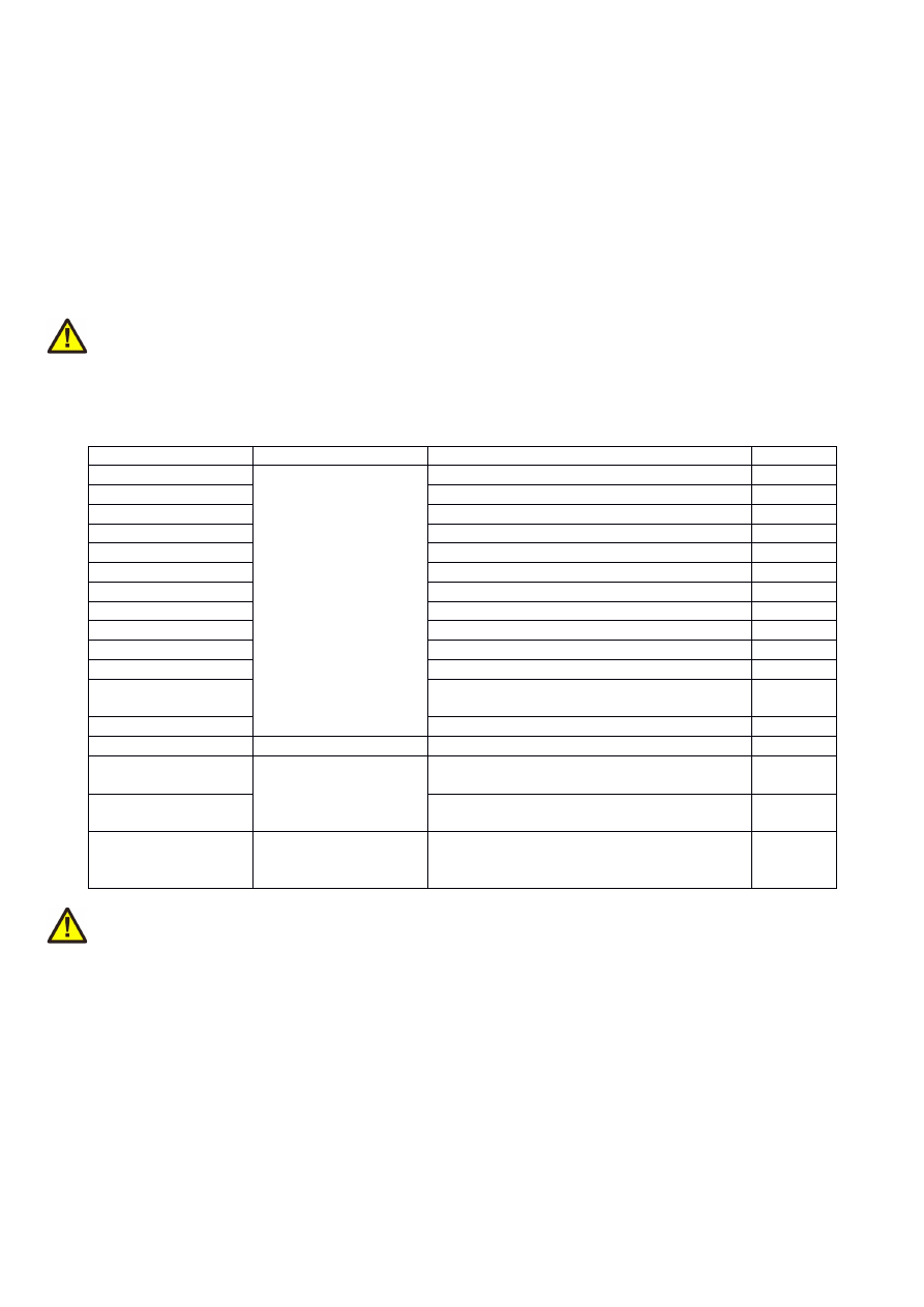
APPENDIX A – Wiring between E1701 and specific laser
types
This appendix describes the wiring between the controller card and specific laser models when the E170Xdock
(as described in “6.6 E1701dock Extension Board”) is not used or when it can’t be used because the laser comes
with a non-standard, proprietary control interface.
Wiring between IPG YLP Series Type B, B1 and B2, GZTech YFPN series fiber
laser
PLEASE NOTE: this wiring scheme is a non-binding policy, it may be incorrect due to changes in connected
hardware. So in every case please check this table against specification and wiring documentation of the used
laser!
Variant using E1701A or E1701D Baseboard, LP8 Extension Board and optional Digi I/O Extension Board for
laser alarms and pilot laser.
Signal Name
Board
Connector / Pin
IPG Pin
LP0
LP8 Extension Board
Pin 1
Pin 1
LP1
Pin 3
Pin 2
LP2
Pin 5
Pin 3
LP3
Pin 7
Pin 4
LP4
Pin 9
Pin 5
LP5
Pin 11
Pin 6
LP6
Pin 13
Pin 7
LP7
Pin 15
Pin 8
MO / Main Oscillator
Pin 8
Pin 18
LP8 Latch
Pin 17
Pin 9
LaserA / Frequency
Pin 22
Pin 20
Laser Gate /
Modulation
Pin 26
Pin 19
LaserB
Pin 19
Pin 22 *)
Alarm,
one of DIn0…DIn7
Digi I/O Extension
Board
Pin 4, 6, 8, 10, 12, 14, 16 or 18
Pin 16
Alarm,
one of DIn0..DIn7
Pin 4, 6, 8, 10, 12, 14, 16 or 18
Pin 21
Pilot Laser: in
software choose
LaserB as output
*) may require additional power driver since some laser variants consume a current at this input which is higher
than the maximum output allowed
In this wiring-scheme no GND-connections are listed, they have to be added in order to get valid and working
connections.
108

Wiring between E1701 and JPT YDFLP series fiber laser (“MOPA”) or IPG YLP
Series Type D fiber laser or Raycus RFL PMX/PQB Series fiber laser
PLEASE NOTE: this wiring scheme is a non-binding policy, it may be incorrect due to changes in connected
hardware. So in every case please check this table against specification and wiring documentation of the used
laser!
Variant using E1701A or E1701D Baseboard, LP8 Extension Board and optional Digi I/O Extension Board for
laser alarms and pilot laser.
Signal Name
Board
Connector / Pin
JPT D-SUB25 Pin
LP0
LP8 Extension Board
Pin 1
Pin 1
LP1 / serial data
Pin 3
Pin 2
2
)
LP2 / serial clock
Pin 5
Pin 3
2
)
LP3
Pin 7
Pin 4
LP4
Pin 9
Pin 5
LP5
Pin 11
Pin 6
LP6
Pin 13
Pin 7
LP7
Pin 15
Pin 8
MO / Main Oscillator
Pin 8
Pin 18
LP8 Latch
Pin 17
Pin 9
LaserA / Frequency
Pin 22
Pin 20
Laser Gate / Modulation
Pin 26
Pin 19
LaserB / serial enable
Pin 19
Pin 22
1
)
2
)
Alarm,
one of DIn0…DIn7
Digi I/O Extension
Board
Pin 4, 6, 8, 10, 12, 14, 16 or 18
Pin 16
Alarm,
one of DIn0…DIn7
Pin 4, 6, 8, 10, 12, 14, 16 or 18
Pin 21
Pilot Laser: in software
choose LaserB as output
1
) for details regarding double-usage of this pin, please refer to the manual of the laser
2
) serial data transmission requires firmware version 28 or newer
In this wiring-scheme no GND-connections are listed, they have to be added in order to get valid and working
connections.
109
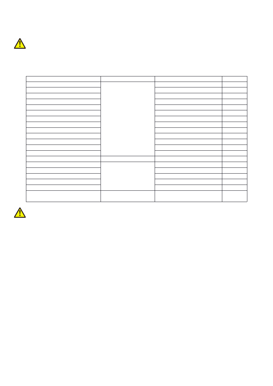
Wiring between E1701 and IPG YLP Series Type E fiber laser
PLEASE NOTE: this wiring scheme is a non-binding policy, it may be incorrect due to changes in connected
hardware. So in every case please check this table against specification and wiring documentation of the used
laser!
Variant using E1701A or E1701D Baseboard, LP8 Extension Board and Digi I/O Extension Board for laser
alarms and pilot laser with support for APD index setting via DB-25 serial data interface
Signal Name
Board
Connector / Pin
IPG Pin
LP0
LP8 Extension Board
Pin 1
Pin 1
LP1
Pin 3
Pin 2
LP2
Pin 5
Pin 3
LP3
Pin 7
Pin 4
LP4
Pin 9
Pin 5
LP5
Pin 11
Pin 6
LP6
Pin 13
Pin 7
LP7
Pin 15
Pin 8
MO / Main Oscillator
Pin 8
Pin 18
LP8 Latch
Pin 17
Pin 9
LaserA / Frequency
Pin 22
Pin 20
Laser Gate / Modulation
Pin 26
Pin 19
LaserB
Pin 19
Pin 22
1
)
Alarm, one of DIn0..DIn7
Digi I/O Extension
Board
Pin 4, 6, 8, 10, 12, 14, 16 or 18
Pin 16
Alarm, one of DIn0..DIn7
Pin 4, 6, 8, 10, 12, 14, 16 or 18
Pin 21
Serial Enable
Pin 7
Pin 24
2
)
Serial Clock
Pin 9
Pin 13
2
)
Serial Data
Pin 11
Pin 10
2
)
Pilot Laser: in software choose
LaserB as output
1
) may require additional power driver since some laser variants consume a current at this input which is higher
than the maximum output allowed
2
) serial data transmission requires firmware version 28 or newer
In this wiring-scheme no GND-connections are listed, they have to be added in order to get valid and working
connections.
110
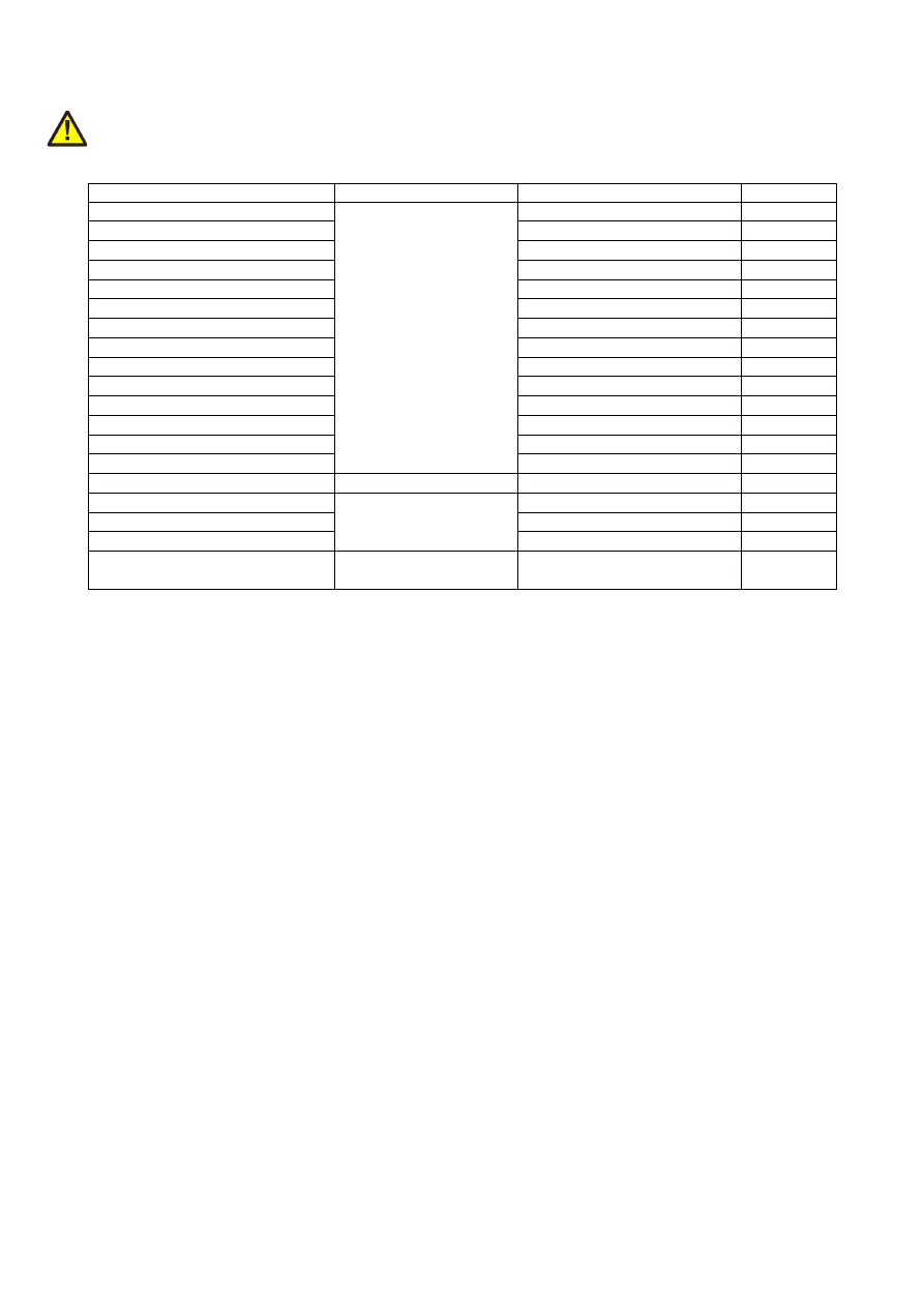
Wiring between E1701 and IPG YLP Series Type F fiber laser
PLEASE NOTE: this wiring scheme is a non-binding policy, it may be incorrect due to changes in connected
hardware. So in every case please check this table against specification and wiring documentation of the used
laser!
Signal Name
Board
E1701D Connector / Pin
D-SUB25
LP0
LP8 Extension Board
Pin 1
Pin 1
LP1
Pin 3
Pin 2
LP2
Pin 5
Pin 3
LP3
Pin 7
Pin 4
LP4
Pin 9
Pin 5
LP5
Pin 11
Pin 6
LP6
Pin 13
Pin 7
LP7
Pin 15
Pin 8
MO / Main Oscillator
Pin 8
Pin 18
LP8 Latch
Pin 17
Pin 9
LaserA / Frequency
Pin 22
Pin 20
Laser Gate / Modulation
26 pin connector, pin 26
Pin 19
LaserB
Pin 19
Pin 22
GND
Pin 2 or 23
Pin 14
Alarm, one of DIn0…DIn7
Digi IO Extension Board
Pin 4, 6, 8, 10, 12, 14, 16 or 18
Pin 11
Alarm, one of DIn0…DIn7
Pin 4, 6, 8, 10, 12, 14, 16 or 18
Pin 16
Alarm, one of DIn0…DIn7
Pin 4, 6, 8, 10, 12, 14, 16 or 18
Pin 21
Pilot Laser: in software choose
LaserB as output
111
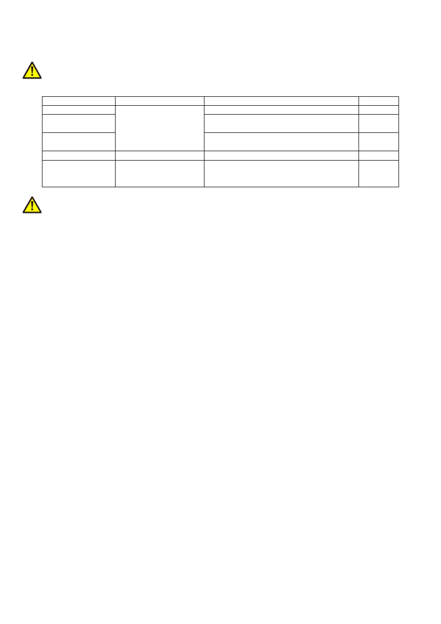
Wiring between E1701 and IPG YLR Series laser
PLEASE NOTE: this wiring scheme is a non-binding policy, it may be incorrect due to changes in connected
hardware. So in every case please check this table against specification and wiring documentation of the used
laser!
Signal Name
Board
Connector / Pin
IPG Pin
AOut0
LP8 Extension Board
Pin 10
Pin 12
1
)
MO / Main
Oscillator
Pin 8
Pin 18
Laser Gate /
Modulation
Pin 26
Pin 15
Pilot Laser,
one of
DOut0..DOut7
Digi I/O Extension Board Pin 3, 5, 7, 9, 11, 13, 15 or 17
Pin 17
1
) maximum analogue output voltage of LP8 extension is limited to 5V while this laser type expects 0..10V
range. So this voltage needs to be doubled by some external equipment, elsewhere the laser can be driven with
a maximum of 50% power only
In this wiring-scheme no GND-connections are listed, they have to be added in order to get valid and working
connections.
112
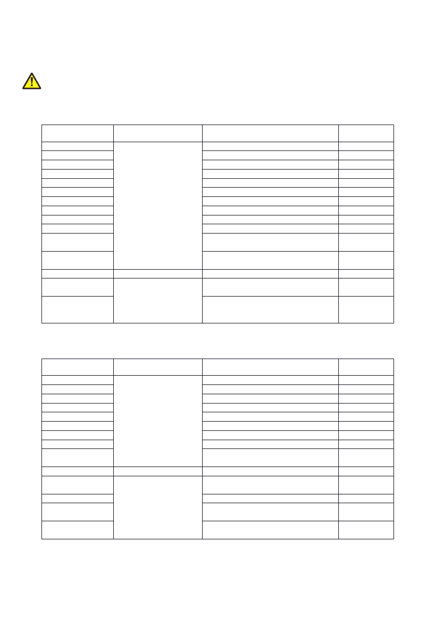
Wiring between E1701 and SPI G4 Pulsed Fibre Laser / TRUMPF TruPulse
nano series
PLEASE NOTE: this wiring scheme is a non-binding policy, it may be incorrect due to changes in connected
hardware. So in every case please check this table against specification and wiring documentation of the used
laser!
Variant 1: waveform selected via LP8 outputs of LP8 Extension Board, simmer, power and extended parameter
control via laser controller plug in/serial interface:
Signal Name
Board
Connector / Pin
SPI Laser
Connector Pin
LP0
LP8 Extension Board
Pin 1
Pin 17
LP1
Pin 3
Pin 18
LP2
Pin 5
Pin 19
LP3
Pin 7
Pin 20
LP4
Pin 9
Pin 51
LP5
Pin 11
Pin 52
LP6
Pin 13
Pin 53
LP7
Pin 15
Pin 54
MO / Laser Enable
Pin 8
Pin 7
LP8 Latch
Pin 17
Pin 23
LaserA / Pulse
Trigger
Pin 22
Pin 47
Laser Gate /
Modulation
Pin 26
Pin 5
Alarm,
one of DIn0…DIn7
Digi I/O Extension Board
Pin 4, 6, 8, 10, 12, 14, 16 or 18
Pin 9
Pilot Laser,
one of DOut0…
DOut7
Pin 3, 5, 7, 9, 11, 13, 15 or 17
Pin 6
Variant 2: waveform selected via digital outputs of Digi I/O Extension Board, simmer, power and extended
parameter control via laser controller plug in/serial interface:
Signal Name
Board
Connector / Pin
SPI Laser
Connector Pin
DOut0
Digi I/O Extension Board
Pin 3
Pin 17
DOut1
Pin 5
Pin 18
DOut2
Pin 7
Pin 19
DOut3
Pin 9
Pin 20
DOut4
Pin 11
Pin 51
DOut5
Pin 13
Pin 52
DOut6
Pin 15
Pin 53
DOut7
Pin 17
Pin 23
Alarm,
one of DIn0…DIn7
Pin 4, 6, 8, 10, 12, 14, 16 or 18
Pin 9
Pilot Laser,
one of LP8_0…P8_7
LP8 Extension Board
Pin 1, 3, 5, 7, 9, 11, 13 or 15
Pin 6
MO / Laser Enable
Pin 8
Pin 7
LaserA / Pulse
Trigger
Pin 22
Pin 47
Laser Gate /
Modulation
Pin 26
Pin 5
113

Variant 3: waveform selection, simmer, power and extended parameter control via laser controller plug in/serial
interface:
Signal Name
Board
Connector / Pin
SPI Laser
Connector Pin
MO / Laser Enable
LP8 Extension Board
Pin 8
Pin 7
LaserA / Pulse
Trigger
Pin 22
Pin 47
Laser Gate /
Modulation
Pin 26
Pin 5
Alarm,
one of DIn0…DIn7
Digi I/O Extension Board Pin 4, 6, 8, 10, 12, 14, 16 or 18
Pin 9
Pilot Laser,
one of LP8_0..LP8_7
or
one of DOut0…
DOut7
LP8 Extension Board
or
Digi I/O Extension Board
Pin 1, 3, 5, 7, 9, 11, 13 or 15
or
Pin 3, 5, 7, 9, 11, 13, 15 or 17
Pin 6
In these wiring-schemes no GND-connections are listed, they have to be added in order to get valid and
working connections.
114
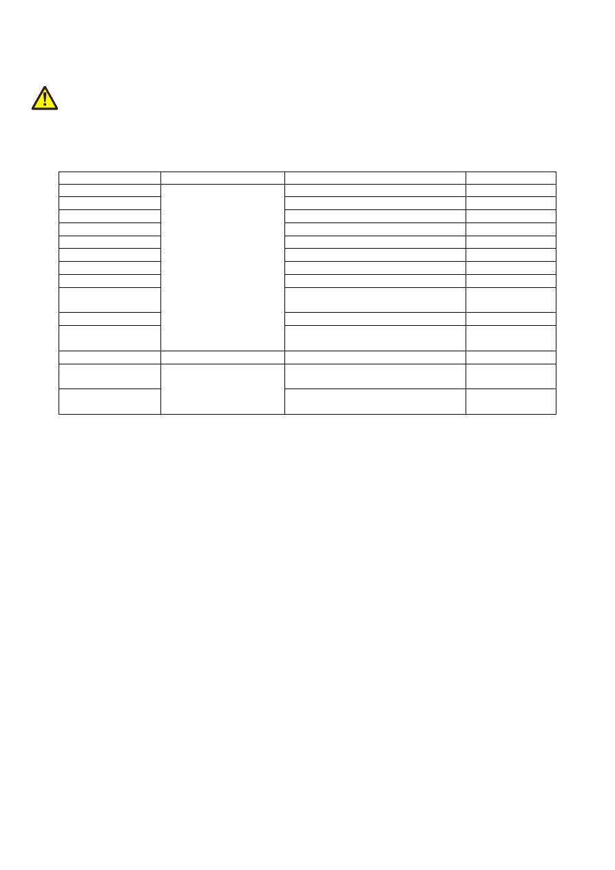
Wiring between E1701 and Raycus fiber laser
PLEASE NOTE: this wiring scheme is a non-binding policy, it may be incorrect due to changes in connected
hardware. So in every case please check this table against specification and wiring documentation of the used
laser!
Variant using E1701A or E1701D Baseboard, LP8 Extension Board and optional Digi I/O Extension Board for
laser alarms and pilot laser.
Signal Name
Board
Connector / Pin
Raycus DB25 Pin
LP0
LP8 Extension Board
Pin 1
Pin 1
LP1
Pin 3
Pin 2
LP2
Pin 5
Pin 3
LP3
Pin 7
Pin 4
LP4
Pin 9
Pin 5
LP5
Pin 11
Pin 6
LP6
Pin 13
Pin 7
LP7
Pin 15
Pin 8
MO / Main
Oscillator
Pin 8
Pin 18
LaserA / Frequency
Pin 22
Pin 20
Laser Gate /
Modulation
Pin 26
Pin 19
Alarm,
one of DIn0…DIn7
Digi I/O Extension Board
Pin 4, 6, 8, 10, 12, 14, 16 or 18
Pin 16
Alarm,
one of DIn0…DIn7
Pin 4, 6, 8, 10, 12, 14, 16 or 18
Pin 21
In this wiring-scheme no GND-connections are listed, they have to be added in order to get valid and working
connections.
115

Wiring between E1701 and MaxPhotonics MFP fiber laser
PLEASE NOTE: this wiring scheme is a non-binding policy, it may be incorrect due to changes in connected
hardware. So in every case please check this table against specification and wiring documentation of the used
laser!
Variant using E1701A or E1701D Baseboard, LP8 Extension Board and optional Digi I/O Extension Board for
laser alarms and pilot laser.
Signal Name
Board
E1701x Pin
MaxPhotonic
s DB25 Pin
LP0
LP8 Extension Board
Pin 1
Pin 1
LP1
Pin 3
Pin 2
LP2
Pin 5
Pin 3
LP3
Pin 7
Pin 4
LP4
Pin 9
Pin 5
LP5
Pin 11
Pin 6
LP6
Pin 13
Pin 7
LP7
Pin 15
Pin 8
LP8 Latch
Pin 17
Pin 9
MO / Main Oscillator
Pin 8
Pin 18
LaserA / Frequency
Pin 22
Pin 20
Laser Gate / Modulation
Pin 26
Pin 19
GND
Pin 2 or 23
Pin 10-15
Alarm,
one of DIn0…DIn7
Digi I/O Extension
Board
Pin 4, 6, 8, 10, 12, 14, 16 or 18
Pin 16
Alarm,
one of DIn0…DIn7
Pin 4, 6, 8, 10, 12, 14, 16 or 18
Pin 21
Pilot Laser, one of DOut0…
DOut7
Pin 3, 5, 7, 9, 11, 13, 15 or 17
Pin 22
In this wiring-scheme no GND-connections are listed, they have to be added in order to get valid and working
connections.
116
Wiring between E1701 and DAVI D-Series RF CO
2
Laser
PLEASE NOTE: this wiring scheme is a non-binding policy, it may be incorrect due to changes in connected
hardware. So in every case please check this table against specification and wiring documentation of the used
laser!
Variant using E1701A or E1701D Baseboard and optional Digi I/O Extension Board for laser alarm.
Signal Name
Board
E1701x Pin
DAVI RJ45 Pin
DAVI RJ45
Wire Colour
LaserA / Frequency
E1701x Baseboard
13
1
orange/white
GND
14
8
brown
Laser Ready input, one of
DIn0…DIn7
Digi I/O Extension Board
Pin 4, 6, 8, 10,
12, 14, 16 or 18
3
green/white
GND
2
6
green
117

Wiring between E1701 and GZTECH S355 series DPSS Laser
PLEASE NOTE: this wiring scheme is a non-binding policy, it may be incorrect due to changes in connected
hardware. So in every case please check this table against specification and wiring documentation of the used
laser!
Variant using E1701D Baseboard.
Signal Name
Board
E1701D Pin
GZTECH DB9
connector Pin
GZTECH Signal Name
LaserA / Frequency
E1701D Baseboard
13
3
PWM
GND
14
5
GND
LaserGate
26
2
Gate
Within BeamConstruct following settings have to be done in order to control the laser:
•
menu “Project” “Project settings” tab-pane “Scanner” button “Configure” parameter “Laser
→
→
→
→
type” has to be set to value “YAG1”
•
menu “Project” “Pen settings” tab-pane “General”: the “Frequency” slider has to be set to an
→
→
appropriate value (typically 30..50 kHz, please refer to the manual of the laser for further details), the
“Power” slider has no effect as no additional power output was configured in scanner controller
settings
•
menu “Project” “Pen settings” tab-pane “Laser”: the parameter “Pulse length” has to be set to an
→
→
appropriate value (such as 1 usec, please refer to the manual of the laser for further details)
To use this laser model with BeamConstruct, HALsetup software package version 8.2-07 or newer is required.
118
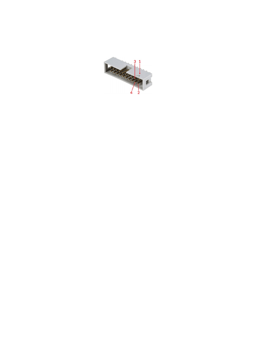
APPENDIX B – IDC connector pin numbering
Pin numbering of the IDC connectors (according to pinout-tables shown in hardware description sections
above) can be seen in below image:
The first pin is marked by a small arrow in connector. Second pin is below of it, counting continues column-wise.
These connectrors itself are standard IDC connectors with 2,54 mm contact spacing.
119
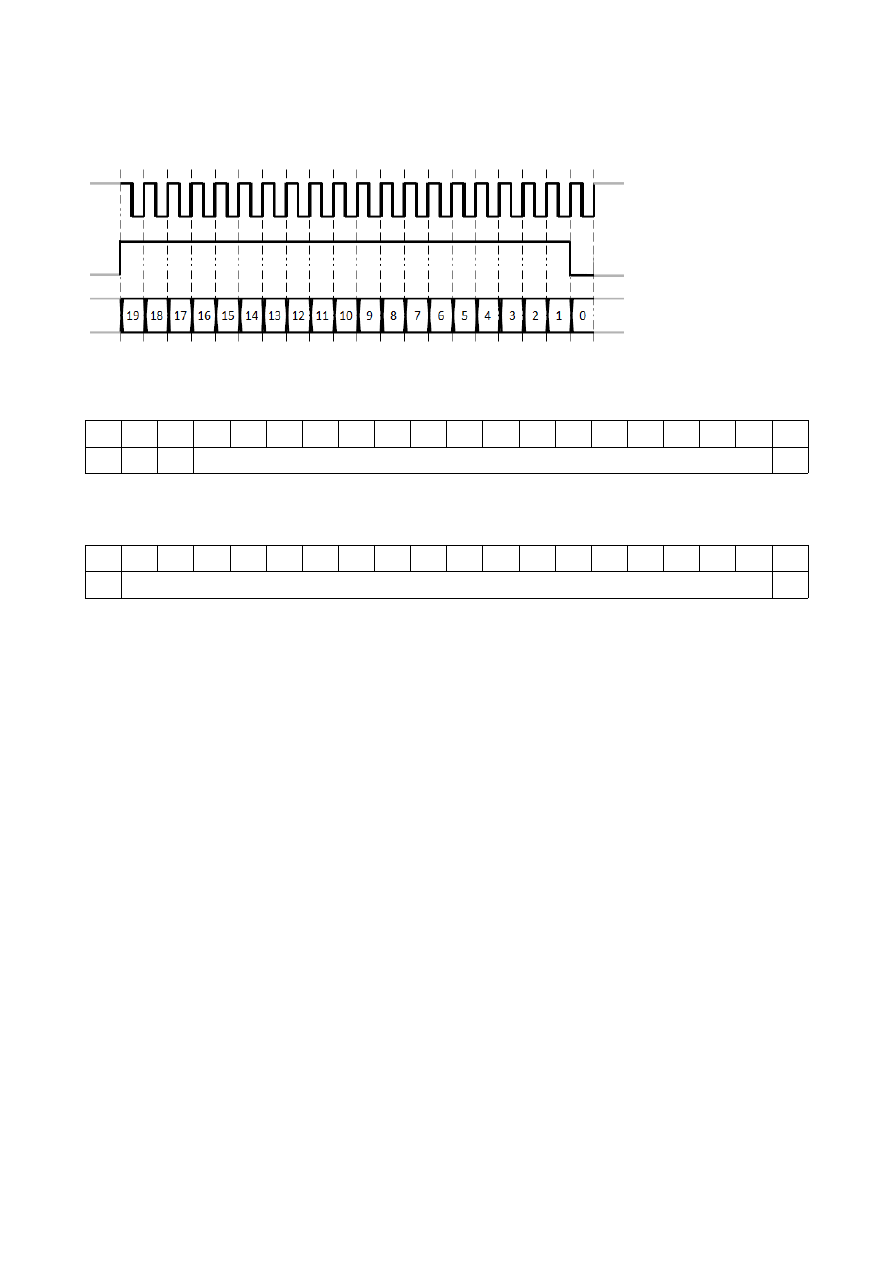
APPENDIX C – E1701D XY2-100 protocol description
The data submitted at 26 pin connector of E1701D are conform to XY2-100 specification:
CLK+
SYNC+
X+, Y+, Z+ Data
In standard 16 bit operating mode first three bits are set to 001, then 16 bit position data followed by a parity
bit (even parity) are transmitted:
19
18
17
16
15
14
13
12
11
10
9
8
7
6
5
4
3
2
1
0
0
0
1
D15..D0 position data
Pe
In enhanced XY2-100 18 bit operating mode first bit is set to 1, then 18 bit position data followed by a parity bit
(odd parity) are transmitted:
19
18
17
16
15
14
13
12
11
10
9
8
7
6
5
4
3
2
1
0
1
D17..D0 position data
Po
To use this mode, the related tune-value has to be set in configuration file (please refer to section “6.1.8
microSD-Card”), this mode requires firmware version 24 or newer
120

APPENDIX D – E1701D XY3-100 protocol description
Depending on the actual configuration, the data submitted at 26 pin connector of E1701D are conform to XY3-
100 specification. For details about the XY3-100 protocol, please refer to
https://sourceforge.net/p/lasia/blog/
.
121

APPENDIX E – E1701D SL2-100 protocol description
The E1701D does not yet support the serial SL2-100 protocol. For further information please contact HALaser
Systems.
122

APPENDIX F – E1701D RL3-100 protocol description
The E1701D does not yet support the RL3-100 protocol. For further information please contact HALaser
Systems.
123
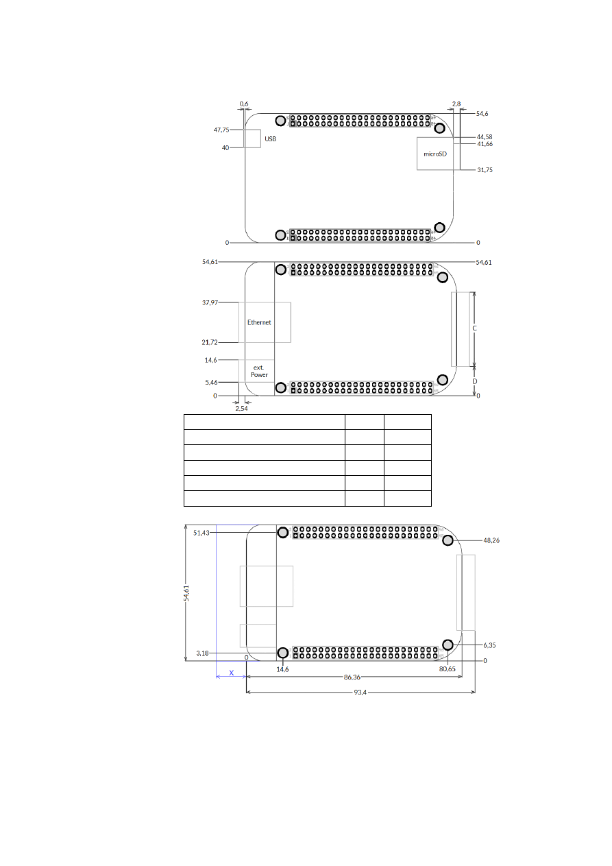
APPENDIX G – Board dimensions
E1701A/E1701D board dimension drawings (baseboard plus optional extension boards), all values are given in
unit mm.
Connectors, bottom view:
Connectors, top view:
Board type
C
D
E1701A Baseboard
40 mm 7,3 mm
E1701D Baseboard
40 mm 7,3 mm
LP8 Extension Board
40 mm 7,3 mm
Digi I/O Extension Board
34 mm 10,3 mm
Secondary Head Extension Board 40 mm 7,3 mm
Dimensions, top view:
X
– for future compatibility leave additional space of 10 mm at Ethernet connector
side of the controller
124
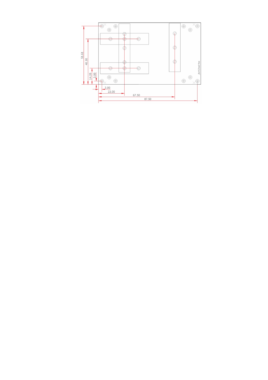
E170Xbase dimension drawing, all values are given in unit mm.
125

Index
1
16-bit IO port - 25
18 bit - 23, 120
1803 - 12
2
2D marking on-the-fly - 44
2D on-the-fly - 22
8
8.3 - 30
A
Alive - 18
analogue output - 11
ASCII - 56
autofile - 21, 32
B
BeamConstruct PRO license - 13, 17
BNC - 50f.
boot - 26
Boot - 18
C
C45 rail - 54
C45 rail adapter - 54
C45 rail lock - 54
cdepr - 58
cdser - 62
cecho - 56
cfror - 60
cftim - 63
cgbds - 56
cgbsr - 57
cgbuf - 59
cgcor - 58
cgepr - 58
cginp - 64
cglog - 56
cgmtx - 60
cgser - 62
cgsta - 63
cgtim - 62
cgtin - 57
cgtxt - 61
chalt - 57
ciser - 62
cjsor - 21, 60
clepr - 33f., 58, 97
CLK - 28
cmsor - 21, 60
CO2 - 10f., 39f.
corrtable - 19, 58
corrtable0 - 19
cpuor - 60
cpwor - 21, 60
126

crrrr - 63
crser - 62
crtim - 62
csao0 - 64
csbuf - 59
cscor - 20, 57
cslgt - 64
cslmo - 64
cslp8 - 64
csmtx - 61
csout - 64
cspof - 61
csser - 62
cssta - 23, 63
cstat - 57
cstdy - 63
csthr - 63
cstim - 62
cstmi - 63
cstmo - 63
cstop - 57
cstrt - 57
cstsc - 63
cstxt - 61
cstyr - 63
cswaf - 26, 61
ctlxy - 59
ctrig - 57
cvers - 56
CW - 10f., 27, 40
D
D-SUB15 - 28
D-SUB25 - 28f.
DataMatrix - 100
DAVI D-Series RF CO2 - 117
Digi I/O - 49
digidebc - 22
digiinit - 21
digimask - 22
digital in- and outputs - 41
dimension drawing - 124f.
dimensions - 124
DIN rail - 54
DIN/C45 rail adapter - 54
DIN/C45 rail lock - 54
Download new firmware - 71
DYN_DATA_MAX_STRING_LENGTH - 99f.
E
E1701_ - 102
e1701.cfg - 74
E1701.cfg - 19
E1701.dat - 19
E1701.fwi - 19
E1701A - 10f., 35
E1701D - 10, 14
E1701dock - 28f.
E1701M - 10
E1701X_ - 102
127

E170X_close() - 74, 97f.
E170X_COMMAND_FLAG_ANA_AOUT0 - 92
E170X_COMMAND_FLAG_DIRECT - 80, 91ff., 96
E170X_COMMAND_FLAG_HIGH_LEVEL - 85
E170X_COMMAND_FLAG_MOTF_WAIT_BITS - 95
E170X_COMMAND_FLAG_MOTF_WAIT_INCS - 95
E170X_COMMAND_FLAG_PASSIVE - 93
E170X_COMMAND_FLAG_SCANNER_VAR_POLYDELAY - 78
E170X_COMMAND_FLAG_SILENT - 85
E170X_COMMAND_FLAG_STREAM - 80, 91ff., 96
E170X_COMMAND_FLAG_WRITE_LASERA_GPO - 96
E170X_COMMAND_FLAG_WRITE_LASERB_GPO - 96
E170X_COMMAND_FLAG_WRITE_LASERGATE - 96
E170X_COMMAND_FLAG_WRITE_LP8LATCH - 96
E170X_COMMAND_FLAG_WRITE_LP8MO - 96
E170X_COMMAND_FLAG_XYCORR_MIRRORX - 75
E170X_COMMAND_FLAG_XYCORR_MIRRORY - 75
E170X_CSTATE_FILE_WRITE_ERROR - 88
E170X_CSTATE_HALTED - 88
E170X_CSTATE_MARKING - 88
E170X_CSTATE_PROCESSING - 88
E170X_CSTATE_SAC_CTLXY - 59, 88
E170X_CSTATE_SAC_MARKING - 59, 88
E170X_CSTATE_SAC_READY - 59, 88
E170X_CSTATE_WAIT_EXTSIGNAL - 85
E170X_CSTATE_WAIT_EXTTRIGGER - 88
E170X_CSTATE_WAIT_INPUT - 88
E170X_CSTATE_WAS_START_PRESSED - 88
E170X_CSTATE_WAS_STOP_PRESSED - 88
E170X_CSTATE_WRITING_DATA - 71
E170X_CSTATE_WRITING_DATA_ERROR - 71
E170X_delay() - 88, 95
E170X_digi_pulse() - 93
E170X_digi_read() - 93
E170X_digi_set_mip_output() - 21, 95
E170X_digi_set_motf_sim( - 95
E170X_digi_set_motf_sim() - 94
E170X_digi_set_motf() - 94f.
E170X_digi_set_wet_output() - 21, 96
E170X_digi_wait_motf() - 95
E170X_digi_wait() - 94
E170X_digi_write() - 93
E170X_dynamic_data2() - 97f.
E170X_ERROR - 102
E170X_ERROR_BORD_NA - 102
E170X_ERROR_FILENAME - 102
E170X_ERROR_FILEOPEN - 102
E170X_ERROR_FILEWRITE - 102
E170X_ERROR_INVALID_CARD - 101
E170X_ERROR_INVALID_DATA - 102
E170X_ERROR_NO_CONNECTION - 101
E170X_ERROR_NO_MEMORY - 101
E170X_ERROR_NOT_SUPPORTED - 102
E170X_ERROR_STILL_IN_PROGRESS - 102
E170X_ERROR_TRANSMISSION - 101
E170X_ERROR_UNKNOWN_BOARD - 102
E170X_ERROR_UNKNOWN_FW - 101
E170X_execute() - 20, 73, 86f.
E170X_FILEMODE_LOCAL - 98
E170X_FILEMODE_SEND - 97f.
128

E170X_FREE_SPACE_PRIMARY - 85, 90
E170X_FREE_SPACE_SECONDARY - 90
E170X_get_card_state() - 85, 87f.
E170X_get_free_space() - 73, 85, 90
E170X_get_library_version() - 91
E170X_get_pos() - 82
E170X_get_serial_number() - 91
E170X_get_startstop_state() - 87
E170X_get_sync() - 86
E170X_get_version() - 90
E170X_halt_execution() - 87f.
E170X_jump_abs() - 81, 95
E170X_LASERMODE_CO2 - 79
E170X_LASERMODE_CRF - 80
E170X_LASERMODE_DFREQ - 80, 89
E170X_LASERMODE_MOPA - 80
E170X_LASERMODE_YAG1 - 79
E170X_LASERMODE_YAG2 - 79
E170X_LASERMODE_YAG3 - 79, 90
E170X_load_correction() - 73f., 98
E170X_lp8_ana_write() - 92
E170X_lp8_write_latch() - 91
E170X_lp8_write_mo() - 92
E170X_lp8_write() - 91
E170X_mark_abs() - 81, 95
E170X_mark_pixelline() - 84
E170X_OK - 101
E170X_PIXELMODE_GATE_POWER_CONTROL - 83
E170X_PIXELMODE_HW_POWER_CONTROL - 83
E170X_PIXELMODE_JUMP_LEAVE_POWER - 83
E170X_PIXELMODE_JUMP_N_SHOOT - 83
E170X_PIXELMODE_NO_JUMPS - 83
E170X_power_callback - 84
E170X_release_trigger_point() - 85, 90, 95
E170X_set_connection() - 73, 82, 96ff.
E170X_set_debug_logfile() - 75
E170X_set_filepath() - 97f.
E170X_set_fpk() - 90
E170X_set_laser_delays() - 78, 83
E170X_set_laser_mode() - 78
E170X_set_laser_timing() - 89
E170X_set_laser() - 80
E170X_set_laserb() - 80, 89
E170X_set_matrix() - 75, 84
E170X_set_overspeed() - 77
E170X_set_password() - 20, 74
E170X_set_pixelmode() - 83
E170X_set_pos() - 82
E170X_set_scanner_delays - 78
E170X_set_scanner_delays() - 78
E170X_set_signal_point() - 85
E170X_set_speeds() - 77
E170X_set_standby() - 89
E170X_set_sync() - 86
E170X_set_trigger_point() - 73, 85, 95
E170X_set_wobble() - 80
E170X_set_xy_correction() - 75
E170X_set_xy_correction2() - 84
E170X_set_z_correction2() - 76
E170X_stop_execution() - 7, 86f.
129

E170X_switch_correction() - 75
E170X_write() - 96
E1803_COMMAND_FLAG_ZCORR_MIRRORZ - 76
electrically insulated - 41
electrostatic sensitive device - 9
enhanced XY2-100 - 23, 120
EPR - 30, 58
Error - 18
ESD - 9
eth - 25
Ethernet - 10f., 14f., 19f., 25, 35
extension - 29, 38, 40, 47
ExtStart - 51, 59, 85, 95f.
ExtStop - 51, 86
F
fiber - 39
fiber laser - 109
fiber lasers - 40
file extension - 30
filename - 30
Firmware - 26
FPK - 10f., 40, 50
G
gateway - 25
grid correction - 10f.
GZTECH S355 series DPSS - 118
GZTech YFPN - 49, 108
H
HALnode Compact Ethernet IO - 25
haltedloop - 21, 32, 34
haltedlooptimeout - 21, 32
I
idxselect - 21, 33f., 58f.
ILDA - 37, 48
in-polygon delay - 78
Interlock - 37
iobuff - 21, 33, 59
iohaltedloop - 21, 32, 34, 58
iolatch - 20, 34
ioselect - 21, 30, 32ff., 58f.
iothres - 20
IP - 14, 19
ip1 - 19
IPG - 10f., 39, 49
IPG YLP - 49, 108ff.
IPG YLR - 112
J
JPT - 49
JPT YDFLP - 49, 109
jump delay - 78, 81
L
Laser LED - 14, 19, 35, 37
laser off delay - 81
laser on delay - 81
130

Laser Show - 107
Laser signals - 39
Laser Signals - 39
LaserA - 40
LaserB - 40
lasergate - 22
Latch - 40
LED - 18, 36
libslrtc4.so - 102
load_correction_file() - 74
loop - 32
LP8 - 24, 40, 48
M
main oscillator - 24
mark delay - 78, 81
Marking Active - 18
marking on-the-fly - 11, 41f.
Marking On-The-Fly - 43
Master Oscillator - 11, 39f.
MaxPhotonics - 49, 116
MaxPhotonics MFP - 49, 116
MFP - 49
Micro-SD - 19
Micro-SD-card - 14, 35
Micro-SD-Card - 19, 37
mipout - 21
MO - 24, 40
MO LED - 39
MOPA - 49, 109
MOPA alarm - 51
N
n_load_correction_file() - 74
netmask - 25
node0 - 25
node1 - 25
NOTE - 14
NTP - 24
O
OLSC - 107
Opto-Configuration - 41, 44
opto-insulated - 42
P
passwd - 20
pethd - 25
polydelay - 78
Power - 14, 35
Power LED - 14, 18f., 35f.
Power supply - 17, 36
pulse-width modulated frequency - 40
PWM - 40, 50
PWM frequency - 10f.
Q
Q-Switch - 10f., 40
quadrature encoder - 11
131

R
Raycus - 49, 115
Raycus RFL-PMX - 49
Raycus RFL-PQB - 49
Reset - 14, 19
RFL-PMX - 49
RFL-PQB - 49
RL3-100 - 123
RTC4 - 102
RTC4DLL.dll - 102
S
ScSCIInitInterface() - 74
SL2-100 - 122
SNTP - 24
SPI - 11
SPI G4 - 113
Stand-Alone - 32
Stand-Alone Control - 34
standalone - 20
Stop - 18
SYNC - 28
T
tune - 22
tunemarkout - 22f., 34
tunereadyout - 22f., 34
turn on laser - 59
Type B - 108
Type D - 109
Type E - 110
Type F - 111
U
USB - 14, 17, 35
USB 2.0 - 10f.
User LEDs - 14, 35
V
value - 96
W
waveform - 113f.
wetout - 21
Windows - 15f.
X
XY2-100 - 49
XY2/100 - 10, 14, 27f.
XY3-100 - 10, 14, 23, 27f., 49, 121
Y
YAG - 10f., 39f.
YAG/CO2 - 50
YDFLP - 49
YLP - 49
.
.bco - 74
132

.crt - 74
.ct5 - 74
.ctb - 74
.fcr - 74
.gcd - 74
.txt - 74
.ucf - 74
.xml - 74
133