The HALswitch R8 board is an easy and quick solution to integrate a scanner controller card into a machine. It makes use of 24V and even 250V directly.
This digital
interface board is designed in a way to allow fast installation: connection to the used scanner controller card requires a 1:1 cable only. After applying 24V power
to the board, it is fully functional and all the digital inputs and outputs can be used with the higher voltages that appear within a machine typically.
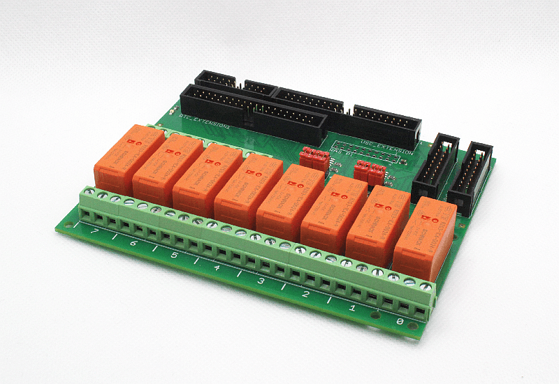
The HALswitch R8 board provides the following features:
- 8 digital inputs and 8 digital outputs, fully galvanically insulated
- a second HALswitch board can be connected to offer additional 2/8 digital inputs and additional 2/8 digital outputs (dependent on used controller card)
- inputs can be operated with 12..24V directly
- outputs can switch up to 250VAC/30VDC and 7A permanent/12A peak
- all outputs act on relays directly with a normally opened and a normally closed contact each
- can be connected to DigiI/O extension board of E1701A / E1701C / E1701D controller card via simple 1:1 cable
- can be connected to digital interface of E1803D scanner controller card via simple 1:1 cable
- can be connected to Intelli-IO extension board of E1803D scanner controller card via simple 1:1 cable
- can be connected to EXTENSION interface of SCAPS™ USC-2™ or USC-3™ control card via simple 1:1 cable
- can be connected to EXTENSION1 interface of Scanlab™ RTC5™ or RTC6™ control card via simple 1:1 cable
- can be connected to GPIO header of a Raspberry Pi™ single-board computer via simple 1:1 cable
- compatible with E1803base for easy mechanical installation
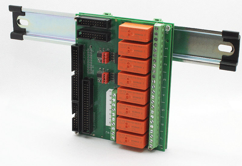
HALswitch R8 mounting example:
- E1803base (in vertical direction and upper mounting position) used to clamp the whole stack onto a DIN/C45 rail
- HALswitch R8 on top allowing to thread the 24V and 250V wires from lower side
Attention: mounting of the HALswitch board has to be done via non-metallic and non-conductive screws/bolts in order to not to break the galvanic insulation the HALswitch board provides!
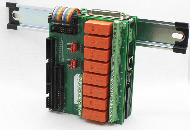
HALswitch R8 mounting example:
- E1803base (in vertical direction and upper mounting position) used to clamp the whole stack onto a DIN/C45 rail
- E1803D controller card which connects via digital interface to HALSwitch board
- E1803base to insulate E1803D controller from HALswitch board
- HALswitch R8 on top connected via flat-belt cable to E1803D and allowing to thread the 24V and 250V wires from lower side
Attention: mounting of the HALswitch board has to be done via non-metallic and non-conductive screws/bolts in order to not to break the galvanic insulation the HALswitch board provides!
Resources
 HALswitch manual containing hardware and usage description as well as full pinout:
halswitch_manual.pdf
HALswitch manual containing hardware and usage description as well as full pinout:
halswitch_manual.pdf
FOR FURTHER INFORMATION, A QUOTATION OR TO ORDER HALswitch RELAY BOARD, PLEASE
CONTACT USHALDrive™ hardware and design is © by HALaser Systems